In this section we are ready to begin looking at the basic electrical tasks that are the foundation of an apprentice role in the electrical industry. These include:
- pre-wiring process, cable support
- electrical installation and testing
- common earthing and equipotential bonding components.
- earth continuity
- installation and testing requirements for earthing and equipotential bonding

What we're covering:
- earthing systems
- the MEN system configurations
- the MEN system components
Two forms of protection against electric shock are recognized. The first of these is termed ‘basic protection’, which is protection against direct contact with live parts and the second is ‘fault protection’, which is protection against indirect contact with a conductive part of an apparatus which is normally dead and earthed, but which has become live due to a fault.
- Basic protection, or direct-contact protection, includes measures to prevent contact with live parts, in particular protection by the insulation of live parts and protection by means of barriers or enclosures.
- Fault protection, or indirect-contact protection can be achieved by automatic disconnection of the supply if the exposed-conductive-parts of equipment are properly earthed.
In an electrical network, an earthing system is a safety measure which protects human life and electrical equipment.
Earthing systems differ from country to country, but with few exceptions, New Zealand uses the Multiple Earthed Neutral (MEN) system for electrical distribution and installations. Refer to these two pieces of legislation:
- Electricity (Safety) Regulations 2010 (Section 1.4).
- AS/NZS3000:2018 (Australian/New Zealand Wiring Rules).
MEN IS A SYSTEM OF EARTHING IN WHICH THE PARTS OF AN ELECTRICAL INSTALLATION REQUIRED TO BE EARTHED IN ACCORDANCE WITH THIS STANDARD ARE CONNECTED TOGETHER TO FORM AN EQUIPOTENTIAL BONDED NETWORK AND THIS NETWORK IS CONNECTED TO BOTH THE NEUTRAL CONDUCTOR OF THE SUPPLY SYSTEM AND THE GENERAL MASS OF EARTH.AS/NZS3000:2018 Clause 1.4.83
In the MEN system of earthing the low voltage neutral conductor is used as the low resistance return path for fault currents and where its potential rise is kept low by having it connected to earth at a number of locations along its length.
The neutral conductor of the distribution system is connected to earth at:
the source of supply (either the generating station or the substation from which electricity, at the voltage at which it is delivered to the consumer, is derived); and regular intervals throughout the supply system; and every electrical installation connected to that system.
Characteristics of the MEN System
- The main earthing electrode is installed in a soil that is effectively conductive.
- The neutral of the supply transformer must be earthed.
- A link connects neutral and earth in the main distribution panel.
- All exposed metal parts in the electrical system are earthed.
Earthing Configurations
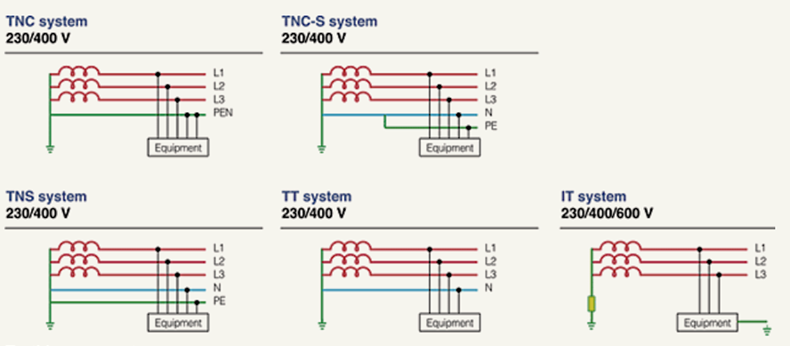
The International Electrotechnical Commission (IEC) uses five basic methods of earthing systems, abbreviated to TN-C, TN-S, TN-C-S, TT and IT, where:
- T stands for earth or terra.
- N for neutral.
- I for isolated.
- S for separate.
- C for combined.
So, in a TN-C (Terra Neutral – Combined) system, Earth and Neutral are combined (also referred to as PEN – protective earth-neutral), whereas in a TN-S system, separate conductors for Earth and Neutral run to consumer loads from the site’s power supply.
A TN-C-S system is very common as it allows the single-phase loads to be supplied by phase and neutral with a completely separate earth system connecting together all the exposed conductive parts before connecting them to the PEN conductor via a main earthing terminal which is also connected to the neutral terminal.
According to AS/NZS3000 TN-C is used for distribution, and (generally) TN-S within the installation. The usual point for the change from TN-C distribution to TN-S installation happens within the installation at the Main Switchboard, specifically at the MEN link. When considering the system as a whole, it is treated as TN-C-S. It is a feature of TN-C systems that the N is earthed at origin and at intervals along its length. The term "MEN" specifically refers to this fact that the N is earthed at multiple places.
Watch the following video explaining the earthing arrangements TN-C-S in a single-phase installation.
Watch
Earthing Arrangements TN-C-S in a Single Phase Installation Explained in Pictures
This video is on TN-C-S Earthing. Pictures show the incoming supply, cut out fuse either 100, 80 or 60 amps the staking of the PEN conductor throughout its run and the external earth fault loop impedance.
Duration: 2.55
Questions
Post Watch Task: Make notes on what you have just heard and if there is anything that you are not sure of, bring it to class to discuss with your classmates and tutor.
TN-C-S System Earthing
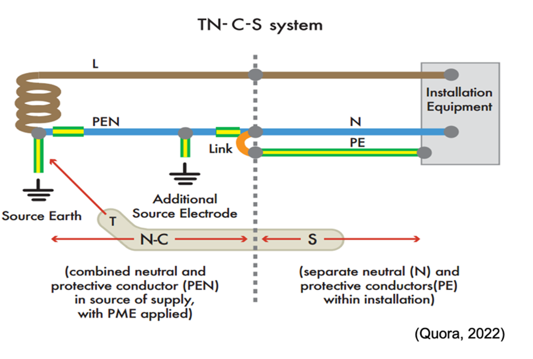
The TN-C-S system, shown above, has the supply neutral conductor of a distribution main connected with earth at source and at intervals along its run. This is usually referred to as protective multiple earthing (PME). With this arrangement the distributor’s neutral conductor is also used to return earth fault currents arising in the consumer’s installation safely to the source. To achieve this, the distributor will provide a consumer’s earthing terminal which is linked to the incoming neutral conductor.
Components of the MEN System
The MEN system of earthing requires an electrical connection to be made between the protective earthing system and the neutral connections of the installation, usually made at the main neutral link in the main switchboard of the installation (MEN connection). The effectiveness of the system depends on:
- The incoming main neutral conductor.
- The MEN link between the main earth terminal bar and the main neutral conductor bar.
- The connection of the main earthing conductor to the earth electrode.
Why is MEN so Important?
- It makes the circuit safe – in an electrical fault where the neutral conductor is disconnected and the active conductor is connected to the exposed metal network, the current flows through the earth conductor to the switchboard, which allows the protective device (such as fuses or circuit breakers) to open circuit and make it safe. In this way the MEN system makes it safe.
- It helps during earth fault currents – When there are earth fault currents, the MEN system uses the network neutral conductor as the conductive path for installation. It is called the ‘earth fault current’ because the fault current of an electric appliance or an equipment goes to the earthed frame.
- It provides an environment for circuit protection to operate correctly – these faults currents should be large so that the protective devices (such as fuses and circuit breakers) can operate. When an Active to Earth fault occurs, the fault path is through the low resistance circuit to the MEN link to the source of power (such as a generator or transformer). The neutral conductor provides the low resistance path so that the power can return. In the absence of the MEN link, the fault current would return via ground.
- It prevents fatal voltage on electrical appliances and exposed metal parts - Earth has a higher resistance than the MEN/neutral conductor path. Thus, the fault current’s capacity would be limited to a degree that it might not be able to operate the protective devices. As a result of this, a fatal voltage can remain on the metallic enclosure of equipment or electrical appliance.
(Electricians Success Academy, 2020)
Despite its popularity, the MEN arrangement could be hazardous if the PEN conductor becomes an open circuit in the supply because the current would not have an immediate path back to sub-station level. Because of this, there are certain installations where it is not allowed to be used – including petrol stations, building sites, caravan parks and some outbuildings.
Activity
Test your learning on the MEN system by completing the following activities.
What we're covering:
- what step and touch voltage are
- power systems earthing
Watch
Step and Touch potential animated video
This video explains Step and Touch Voltage. Awareness of step and touch potential, caused by ground potential rise, is important for anyone working on high-voltage power transmission systems. In a typical SNT application, the transmission line is de-energized and is bonded to the tower to be safe to work on. However, the transmission line itself acts as a very large antenna, and can pick up large amounts of energy which must be shunted to earth ground. And if the tower ground is faulty, the ground potential may rise and a dangerous condition can result.
Duration: 1.53
Questions
Pre-Watch Question: Listen for the definitions of step and touch voltage in the video and write them down when you hear them.
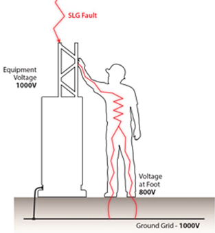
Post Watch Task: Does the picture below show step or touch voltage?

Refer to NZECP: 35:1993 for Power Systems Earthing. This code of practice is intended to provide guidance on acceptable methods for determining the safety of earthing systems associated with works. (Links and explanations for various New Zealand Electrical Codes of Practice (ECPs) can be located at the WorkSafe website.
Section 1.2.14 Step voltage means the difference in surface potential experienced by a person bridging 1 metre with the person’s feet apart, without contacting any other earthed object.
Section 1.2.17 Touch voltage - means the voltage which will appear between any point of contact with uninsulated metalwork located within 2.5 m from the surface of the ground and any point on the surface of the ground within a horizontal distance of 1.25 m from the vertical projection of the point of contact with the uninsulated metalwork.
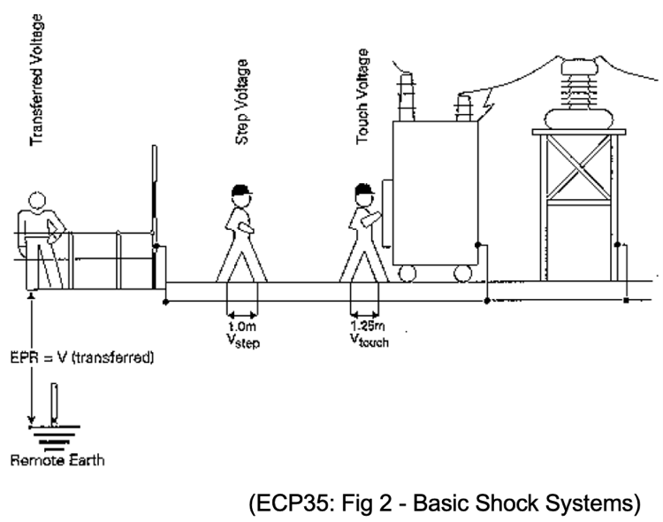
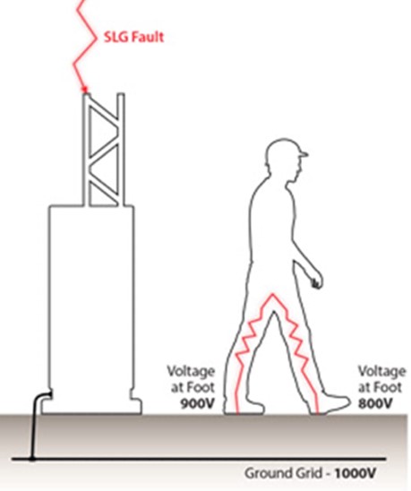
When current flows from an overhead conductor to the earth, a high-voltage condition is created and a voltage gradient will occur based on the resistivity of the soil, resulting in a voltage difference, or potential difference, between two points on the ground. This can cause voltage difference between a person’s feet.

| The diagram below represents a “Step Voltage” of 100 Volts. | The diagram below illustrates a “Touch Voltage” of 200 Volts. |
 |
 |
Activity
Review what you have learned about step and touch voltage in the activity below.

What we're covering:
- difference between earthing and equipotential earthing
- grounding and bonding
Earthing protects you from an electric shock by providing a path (a protective conductor) for a fault current to flow to earth. It also causes the protective device (either a circuit-breaker or fuse) to switch off the electric current to the circuit that has the fault.
The MEN system takes care of most of the electrical installation (electrical cables and equipment), however AS/NZS 3000, 5.4.6 Structural Metalwork and Conductive Building Materials, introduces the requirement to earth ‘at risk’ conductive building elements. (Conductive parts at risk of coming into contact with live cables/equipment or damaged cables.)
Examples of what might need to be earthed are:
- Structural steel frames or members.
- Light steel structural framing.
- Exposed conductive materials, like metal sink/tub or vanity benches etc, with electrical units or equipment in contact.
- Depending on the situation and risk other conductive items like metal cladding/lining, roofing etc.

"Equipotential Bonding is intended to minimise the risk associated with the occurrence of voltage differences between exposed conductive parts of electrical equipment and extraneous conductive parts". (AS/NZS 3000, Section 5.6.1.)
Bonding together conductive parts allows the potential to be almost the same and therefore safer. Without equipotential bonding, if you touch electrical equipment with a fault and also touch metal which is not part of the electrical installation, the potential voltage will not be equal, and in trying to be equal it may want to go to earth through you!
Note: metalwork associated with the electrical installation is known as exposed, while metalwork not associated with the electrical installation is termed extraneous.
What are some examples of extraneous conductive parts requiring equipotential bonding?
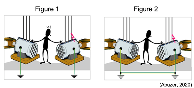
Consider two motors (as shown in Figures 1 and 2) fed by two different power systems (one Low Voltage and the other Medium Voltage). Each motor is earthed.
A person standing on earth (and insulated with respect to the earth) touches both motors simultaneously.
If an earth fault occurs at one motor, the motor body will become alive, and the person will experience a shock. (Figure 1.)
When the motor bodies are bonded (Figure 2), any potential difference will be minimised due to the connection and the person will not receive an electric shock.
Watch
Grounding vs Bonding: Grounding Series (Part 3)
This video explains grounding and bonding.
Duration: 5.46
Questions
Post Watch Task: Write a definition for grounding and bonding and add it to your glossary.
Activity
Check your progress on the topic of earthing and bonding by completing the following learning activities.
Can you complete this puzzle? Write your answers down on a piece of paper and take it to class to compare with your classmates.


What we're covering:
- earth continuity
- leakage and insulation testing
- RCDs
- disconnection times
AS/NZS3000:2007 Electrical Installations Section 8 prescribes the mandatory tests for electrical installations to comply with the regulations, and Clause 8.3 Testing lists the mandatory tests required and broad testing procedures.
In addition to the required visual inspection, the mandatory test requirements for electrical installations are:
- Continuity of the earthing system* (earth resistance of the main earthing conductor, protective earthing conductors and bonding conductors).
- Insulation testing, achieved by either measuring insulation resistance, or leakage current.
- Polarity - confirmation of the correct polarity of live connections in cord sets/cord extension sets with rewireable plugs or rewireable connectors/cord extension sockets.
- Correct circuit connections.
- Verification of impedance required for automatic disconnection of supply (earth fault-loop impedance).
- Operation of RCDs.
Earth Continuity
The Earth Continuity Test, (AS/NZS 3000 8.3.5) is carried out between exposed metal parts of the electrical installation and the earth bar. It is one of the most common product safety tests. It is performed on a product’s electrical grounding system. Testing is mandatory for: Class I equipment; EPODs (electric portable outlet devices); Cord Sets and Extension Sets and RCDs - residual current devices not within the scope of AS/NZS 3003 and NZS 6115.
Earthing continuity is also covered by AS/NZS 3760:2010 2.3.3.:
To confirm that the resistance of the protective earth circuit is sufficiently low to ensure correct operation of the circuit protecting device, the continuity of the protective earthing conductor from the plug earth pin to accessible earthed parts of Class I equipment shall be checked. The continuity of the protective earth conductor between the earth pin of the plug and the earth contact and every outlet(s) of cord sets, cord extension sets, EPODs and PRCDs shall be checked. Such equipment shall be tested in accordance with Appendix D and shall have a measured resistance of the protective earth circuit, or the protective earthing conductor which does not exceed 1Ω.
It is the grounding system that protects the user from a shock hazard during an electrical fault condition. The test identifies excess resistance in the grounding system that could limit the effectiveness of the ground to perform its intended function.
Keep in mind these two objectives:
- Low Resistance: The main objective of the Earth Continuity Test is to verify that the protective ground system has minimal electrical resistance. If an internal electrical fault occurs in the product while in use, ideally all fault current will flow to ground (earth) rather than through the person. Also, by keeping ground resistance low, the fault current remains high, tripping the circuit breaker or fuse as soon as possible.
- Reliable at High Current: To ensure the grounding system continues to operate as intended during a fault condition. The grounding system must be able to hold the fault current until the overcurrent protection for the product is tripped (i.e., circuit breaker).
During the continuity test, a digital PAT/multimeter sends a small current through the circuit to measure resistance in the circuit. If the flow of electrons is not continuous due to damaged components, broken conductors or high resistance, the circuit is considered “open.” Continuity testing must only be attempted when voltage is NOT present in the circuit being tested.
Earth connections need regular testing as they can easily be damaged by a range of factors such as corrosion, loose connections, insulation being crimped under screw terminals or too small a wire being used.
If the earth connection is missing or damaged then an important protection mechanism is diminished or even non-existent, creating a significant safety hazard.
Watch these videos about the Earth Continuity Test and make notes for your own reference.
Earth Continuity Test
Cable Testing: How to test continuity and insulation resistance.
Electrical Capstone Practical Exam Fault Finding-Earth Continuity
Your tutor will show you how to carry out an earth continuity test in class. Make notes about the steps you should follow.
Visual Inspection
Around 90% of faults can be found by inspection alone. Visual Inspection testing involves checking appliances, accessories, connectors, plugs or extension outlet sockets for all manner of other things to ensure they are safe to operate. You will have the opportunity to carry out visual inspections in the workshop.
Earth Leakage Test and Insulation Resistance Test
The integrity of the insulation between live parts and other parts is tested by measuring the leakage current value, or by measuring the insulation resistance value:
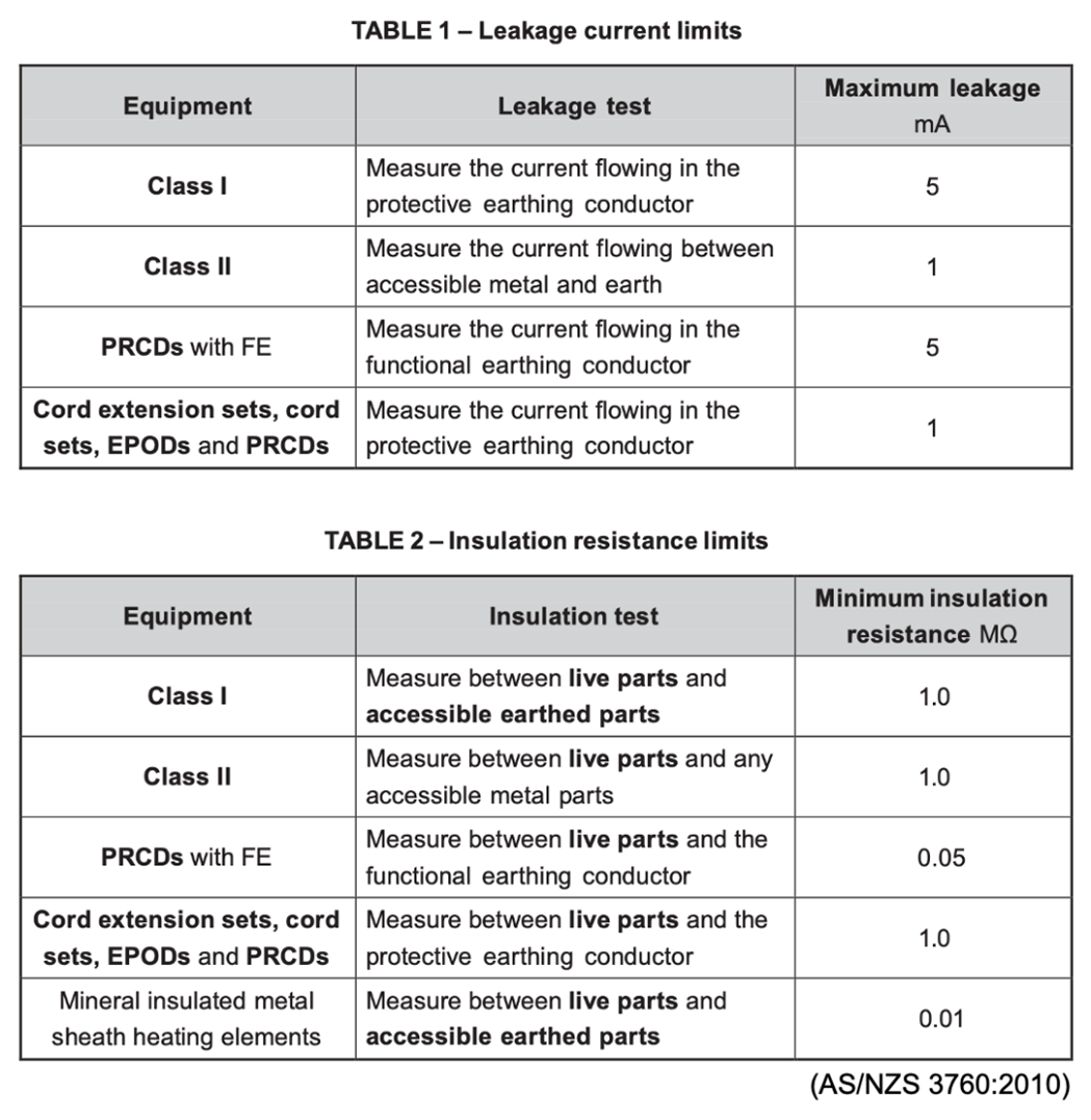
Residual Current Devices (RCDs)
An RCD is an electronic sensing device which constantly monitors the balance of the current flow in the live and neutral conductors to ensure that should even a minor leakage occur the RCD will switch off the power within 300 milliseconds (for personal protection RCDs) i.e., in less than the time of a single heartbeat -which could mean the difference between life and death.
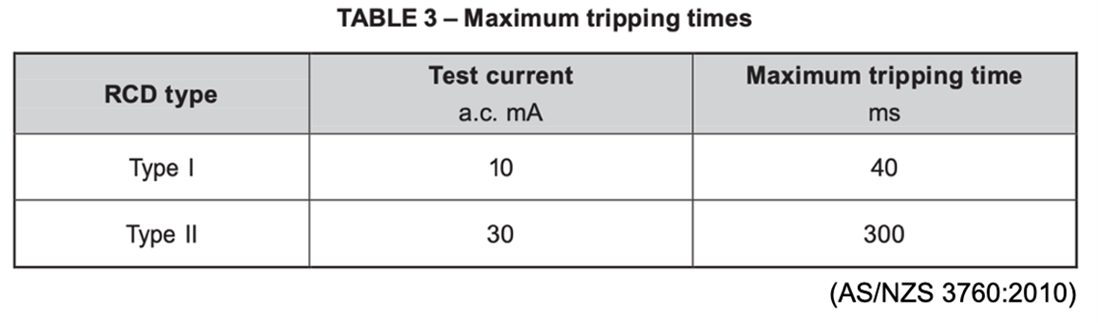
As well as testing for earth continuity and insulation /leakage, RCDs should have a Trip Time test performed on them at the time period specified in AS/NZS3760:2010.
Disconnection Times
The disconnection time, or time taken for a circuit breaker to cut off the electrical supply during a fault, is a big factor in someone surviving an electrical shock. The quicker a circuit can disconnect the supply during a fault, the safer the circuit is.
Be aware however that the longest disconnection times for protective devices, (leading to the longest shock times and the greatest danger), are usually associated with the lowest levels of fault current, and not, as is commonly believed, the highest levels. Why is that do you think?
AS/NZS 3000:2018 1.5.5.3 states the maximum disconnection time for 230/240 V supply voltage shall not exceed the following:
- 0.4 s for final subcircuits that supply -
- socket outlets having rated currents not exceeding 63 A;
- hand-held Class 1 equipment; or
- portable equipment intended for manual movement during use.
- 5 s for other circuits including sub-mains and final subcircuits supplying fixed or stationary equipment.
Maximum disconnection times are set according to the level of risk and will vary for different voltages and installation conditions. 0.4 seconds is roughly the maximum time that 95% of people should be exposed in a left hand to feet shock for a voltage of around 240 V A.C., with a low risk of irreversible physiological side effects, under normal conditions and operating in a "TN" system.
See AS/NZS 3000:2018 Appendix B for detailed description of Disconnection Times.
AS/NZS 4871.1:2012 Figure 1 shows the maximum duration of human exposure to prospective touch voltages that do not usually result in result in harmful physiological effects, under normal conditions (Curve L) and wet conditions (Curve Lp).
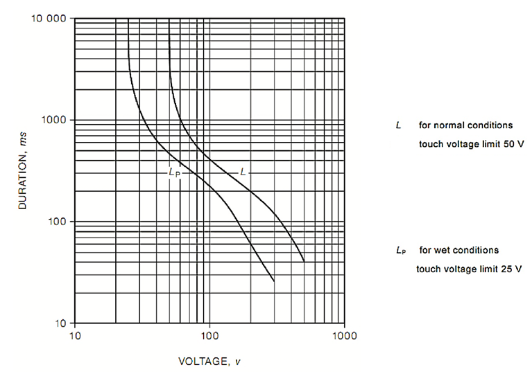
The curves represent the 50 Hz voltage/time duration limits for the majority of the population that will not result in fibrillation (and so electrocution). They are well beyond the threshold of perception and, at a minimum, will result in a painful shock, involuntary movement and loss of normal muscle control that may result in substantial injury as a consequence. They may only be considered ‘safe’ in that the majority of people are unlikely to fibrillate and will recover from the shock without assistance or lasting physiological damage. (World Coal, 2017)
For normal conditions a touch voltage of 50 V can be sustained by a person indefinitely, whereas a touch voltage of 100 V cannot be sustained and must be disconnected.
AS/NZS 3760:2010 (to be superseded by AS/NZS 3760:2022 in June 2023) specifies in-service safety inspection and the testing protocols and criteria that satisfy these obligations and provides a cost-effective approach to safety without jeopardizing personnel safety or involving excessive equipment downtime.
The standard enables persons responsible for the safety of electrical equipment in the workplace to instigate an inspection and testing programme to achieve that aim. It also enables persons undertaking the inspection and testing to carry out the task in a safe and effective manner. (AS/NZS 3760:2010)
It is a requirement under the HSWA legislation for portable devices to be free from defect. Adherence to AS/NZS 3760:2010 is one method of demonstrating work health and safety legislation compliance.
Activity
