In this topic we will be introducing conductors, insulators, semi-conductors and resistors. We will:
- Outline the nature of conductors, insulators, semiconductors, and their use in the electrical industry.
- Explain the fundamental principles of voltage, current, resistance, and the effects of electrical energy.
- Define the term conventional current flow with reference to electron flow.

What we're covering:
- revision of atomic structure
- conductors
- insulators
- semiconductors
Let’s start by revising atomic structure and how this relates to electricity. The following 3-part video is excellent when it comes to explaining the basics. Watch all three parts - more than once if you need to.
- Part One: The Structure of an Atom
- Part Two: The Atomic Structure of Copper
- Part Three: Which Way Do Electrons Flow?
Now test your knowledge by completing the 10-question quiz here:
Conductors
In electrical engineering, a conductor is defined as an object or type of material that allows the flow of charge in one or more directions. Conductors have low resistance and transfer electric current well. Their loosely held valence (outer) electrons move freely through the material, responding to nearby positive and negative charges.

Metals are generally good conductors, with silver the best. Gold is also an excellent conductor but the high cost of these two precious metals means they are not commonly used. Copper is the most widely used conductor in wires. Although aluminium is a better conductor than copper, it is not used in household wiring as its thermal properties have resulted in electrical fires. Aluminium is used in long distance power lines, since its light weight makes it possible to create very long, light wires with low resistance. Other metal conductors include tungsten, lead and tin.
Other electrical conductors include metal alloys, electrolytes, some non-metals like graphite (a form of carbon) and conductive polymers.
Activity
Find out what these terms mean and give two examples of each. Share your results in the forum:
- Metal alloy
- Electrolyte
- Conductive polymer.
Such materials allow the current flow due to the presence of free electron or ions which starts moving when voltage is applied. Conductors have very low electrical resistance (opposition to current flow) although resistance will depend on depend on length and width of the conductor and temperature.
Insulators
Insulators are materials with a high resistance that does not allow the flow of current. Electrons are bound very tightly to the atoms or molecules that make up the material, making it impossible to transfer charge from one place to another within the material. They are used for protection against electric shock. Insulators include quartz, mica, glass, plastics, ceramics, rubber, wood, oil and paper.
Activity
Find out what these insulating materials are made from. Share your findings in the forum.
- Quartz
- Mica
- Ceramic
Semiconductors
Most materials can be classified as either conductors or insulators. Semiconductors are materials that have conductivity in-between conductors and insulators and pass a limited amount of electrical current. They can block or allow the current flow under different conditions. Electrons are shared in semi- conductors, with only a small number of free electrons available.
Semi-conducting materials are generally crystalline solids like silicon, graphite (carbon) and germanium.
Semiconductors are extremely important in electronics where they are used to control the amount of current in an electrical system. Semiconductors can be “doped” or mixed with different types of materials to change their conductive properties.
Watch this video explaining conductors, insulators and semi-conductors.
Activity
For the following activity, drag the correct answer to the appropriate spot to describe the characteristics of conductors, insulators and semiconductors. Use the arrows to progress through all seven activities.
This week's worksheet answers here.
What we're covering:
- Voltage
- Current
- Resistance
We have discussed the terms voltage, current and resistance in earlier modules. Now let’s build on that knowledge and the relationship between the three parameters.

Electricity results when electrons are pushed and pulled from atom to atom. Electrons create charge, which we harness to do work. When we talk about voltage, current and resistance, we are describing the movement of charge, and therefore, the behaviour of electrons.
Read this article, Voltage, Current, Resistance, and Ohm's Law, before going further:
The article uses a water tank with a hose on the bottom to describe voltage, current, and resistance:
- The water tank is the battery that stores energy.
- Water in the tank represents Charge.
- Pressure at the end of the hose represents Voltage.
- Flow is the Current.

The more water in the tank, the higher the charge, and the more pressure (voltage) is measured at the end of the hose. Reducing the amount of water lowers the pressure at the end of the hose – i.e., decreases the voltage.
A decrease in the amount of water will also decrease flow through the hose. Or in electrical terms, reducing pressure (voltage) reduces water flow (current).
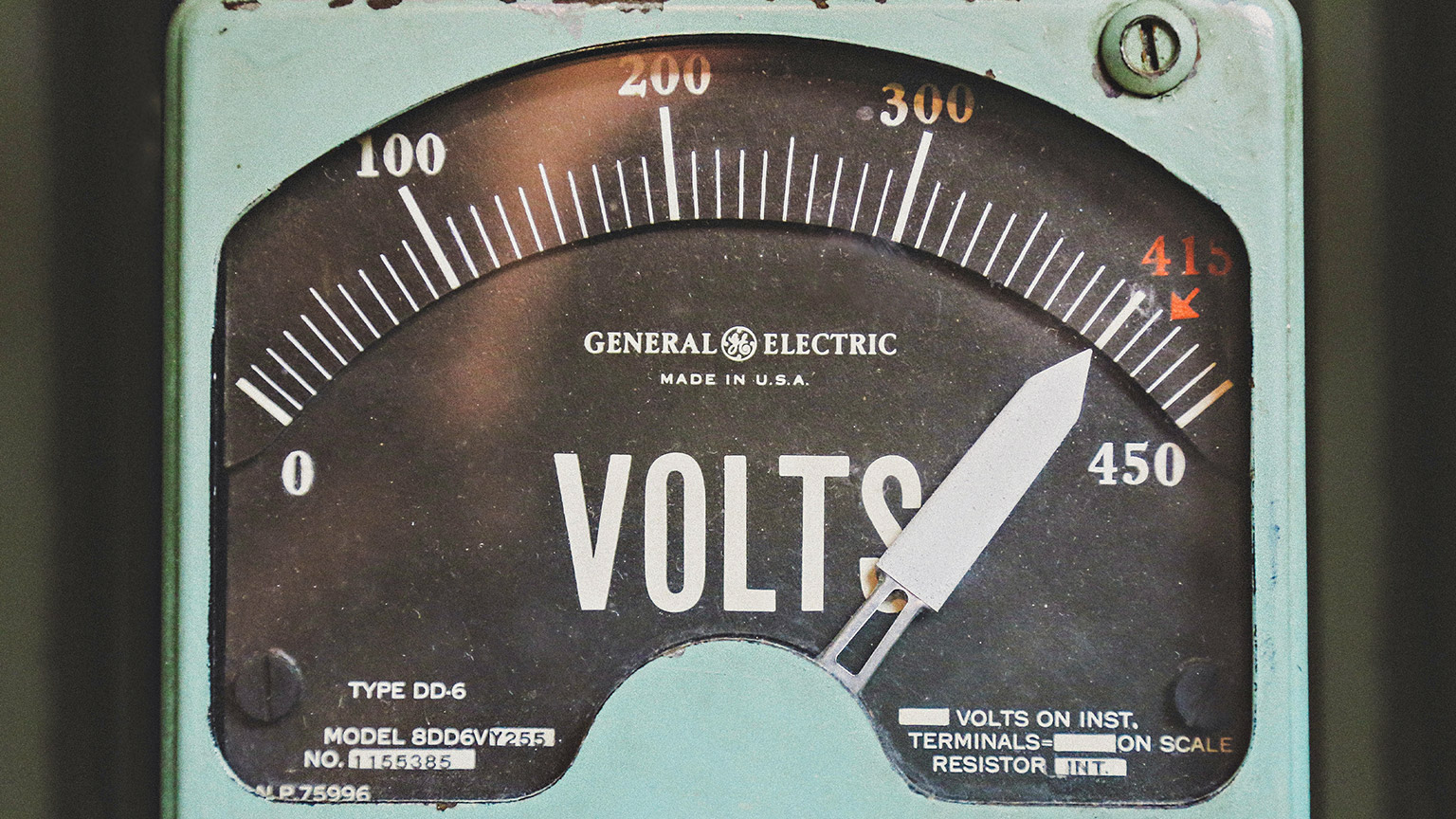
Voltage
Voltage is defined as the amount of potential energy between two points on a circuit, where one point has more charge than the other. It represents the possibility for energy release as the electrons move from one point to another. (There may not be any actual movement of electrons occurring – think of a battery.)
Voltage may also be described as the pressure from an electrical circuit's power source that pushes charged electrons (current) through a conducting loop, enabling them to do work such as illuminating a bulb.
This power source can generate voltage in various ways such as chemical reactions (in batteries), radiant energy (in solar cells), and the influence of magnetism on conductors (generators).
Example of voltage in a simple DC circuit:
- Switch is closed (turned ON).
- The "potential energy difference" between the battery's two poles - is activated, creating a pressure that forces electrons to flow from the battery's negative terminal.
- Current reaches the light, causing it to glow.
- Current returns to the power source.

The potential energy difference between two points in a circuit is expressed in volts and identifies how much work, potentially, can be done through the circuit. For example, a household AA alkaline battery offers 1.5 V, whereas typical household electrical outlets offer 230 V. The greater the voltage in a circuit, the greater its ability to "push" more electrons and do work.
Current
Thinking back to the water tank, current = flow. Current is the rate at which electrons (or electrical charge) flow past a point in a complete electrical circuit. Current has the symbol I and is measured in amperes, or amps (A). A current of 1 A means that 1 coulomb of electrons, which is 6.24 x 10¹⁸ electrons, moves past a single point in a circuit in 1 second.
Watch this video: What is Electric Current?
Electrons flow through a conductor when two conditions of an electric circuit are met:
- The circuit includes an energy source that produces voltage. Without voltage, electrons move randomly and fairly evenly within a wire, and current cannot flow. Voltage creates pressure that drives electrons in a single direction. Different voltage sources produce different amounts of current e.g., standard household batteries (AAA, AA, C and D) produce 1.5 volts each.
- The circuit forms a closed, conducting loop through which electrons can flow, providing energy to any device (a load) connected to the circuit. A circuit is closed (complete) when a switch is turned to the ON, or closed, position.
Recall from Course One – current can be alternating or direct.

Direct Current (DC) refers to current and voltage whose direction does not change. A typical example is the electricity provided by batteries. With a direct current, the voltage is always positive (or always negative), and the current always flows in the same direction. A device won’t work if its battery is installed with the poles reversed.
Alternating Current (AC) refers to current and voltage whose direction and magnitude vary regularly over time. AC flows in a sine wave pattern, reversing direction at regular intervals. AC electricity is used by the power grid, for example in household outlets. However, most standard electronic devices convert it into DC current with their internal circuitry.
Do you remember why the power grid use AC current for transmission?
Resistance
Learn about the relationship between Voltage and Current in this video.
We have seen that the higher the voltage, the more current will flow. Resistance is another property that affects current. Think of resistance as the width through which electrons flow. The narrower the width through which the electrons must flow, the greater the resistance and therefore lower the current. (Recall the steel wool used in the video to impeded the water flow in the tube.) Resistance decreases as the width through which electrons can flow increases, allowing more current to flow at once.

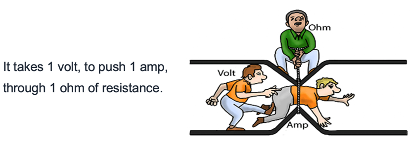
Resistance is a measure of a material's tendency to resist the flow of charge (current).
When 1 volt produces 1 ampere of current in an object, the resistance is 1 ohm (symbol is omega).

An ohm is a very small unit of resistance; a conductor might have a resistance of one or two ohms, whereas insulators have ohm measurements in the billions. All materials except superconductors have some resistance; conductors have low resistance, while insulators have high resistance levels.
The resistance in a wire increases as:
- The length of the wire increases.
- The thickness of the wire decreases.
- The temperature increases.

What we're covering:
- conventional flow and electron flow
- dry cell batteries
One of the confusing ideas when you are starting out as an electrical engineer is conventional current direction.

Conventional Current is explained in both the following videos.
Conventional Current VS Electron Flow - GCSE Physics
What is Electricity? Part 3: Which Way Do Electrons Flow?
Activity

- Label the directions of both electron flow and conventional flow in this simple circuit.
- How do we define Conventional flow?
- How do we define Electron flow?
- Write an explanation, (using your own words), describing the two completely opposite systems for labelling the direction of electric current. (What historical events led to this confusion, and why does it still exist today? Which system should we use?)
Put your answers in the forum. (Take a screenshot of the image and load it onto a word document so that you can label it easily)
Dry Cell Batteries
Activity
Prepare an A4 poster explaining how a battery works. Your poster should include:
- A fully labelled diagram of the cross-section of a battery.
- A brief explanation of the three main components of a battery – anode, cathode and electrolyte.
- Ordered steps explaining the process of generating electric power with a battery.
- What happens when a battery becomes ‘flat’?
Present your poster in the class forum.