
Before starting to read and interpret plans, an essential step is to confirm whether plans, specifications, and amendments are the current versions. As construction personnel tasked with reading and interpreting the plans, you must ensure that the details in the plans and specifications you have at hand are updated and incorporate the latest amendments. Failing to do so will lead to the communication of outdated and erroneous information, which can potentially escalate into problems including, but not limited to, the following:
- Mistakes in the developing cost estimates
- Purchase of non-compliant materials, building non-compliant structure
- Faulty installation of construction elements
- Incurred costs for addressing and rectifying faults caused by the failure to incorporate updates in the plans and specifications
Before diving deeper into the process of confirming the current versions of essential documents, you must first know what plans, specifications, and amendments are.
Plans
Plans are documents that contain construction drawings that serve to provide a visual representation of the building project. They contain information such as the sizes and dimensions of construction elements, installation details of materials, and layout of components (e.g. building position, piping). They are usually printed on large sheets, especially when the building project is large and complex. However, some organisations prefer to use computer-aided design (CAD) file format to incorporate changes and updates more easily.
Generally, plans are categorised into the following:
- Concept drawing/sketches
- Architectural plans
- Structural plans
- Civil plans
- Mechanical plans
- Electrical plans
- Plumbing and draining plans
- Utilities and services plans
- Landscape plans, etc.
These types of plans will be discussed in the following sections.
Specifications
As opposed to plans, specifications are documents that contain a textual description of the drawings found in the construction plans. Specifications help explain the drawings found in the construction plans and present additional information that cannot be expressed clearly through drawings. Examples include, but are not limited to, the following:
- The structural strength of concrete, steel, and other structural elements
- Technical details of a product (e.g. brand, colour, dimensions, etc.)
- Step-by-step instructions for doing a specific job
- Allowable tolerances for the installation of parts
- Safety procedures
- Necessary licences or qualifications of relevant construction personnel.
Take note that the length and level of detail of the specifications document highly depend on the complexity of the project. For example, in the case of a residential project, the specifications documents will only consist of a few pages compared to the specifications for a commercial project. Specification documents complement the construction plans. Together with the plans, they form legal parts of the contract.
Amendments
As a building and construction project progresses, changes or revisions will most probably occur. Some examples include clients changing the dimensions of spaces based on their preference or contractors changing material specifications due to the unavailability of some construction supplies. These changes are more formally referred to as amendments. Amendments need to be documented and reflected in the construction plans and specifications to inform all parties involved in the construction project.
Confirming the currency of plans and amendments
In confirming the currency of plans and amendments, it is essential to know the relevant industry personnel you need to contact. You are expected to work with the appropriate personnel who had developed the construction plans.
At all times, follow your organisation’s policies and procedures in contacting the relevant personnel mentioned.
Below is the process of confirming the currency of plans and amendments:
(Note: The sample plan used as an example can be viewed here.)
Step 1
Meet with the appropriate personnel who had developed the construction plans. You can refer to the table below for the personnel corresponding to the types of plans to be confirmed.
| Types of plan | Appropriate personnel to confirm plans with |
|---|---|
| Architectural | Architect |
| Structural | Structural Engineer |
| Mechanical | Mechanical Engineer |
| Electrical | Electrical Engineer |
| Plumbing and drainage | Plumbing Engineer |
| Utilities and Services | Civil Engineer; Contractor |
Step 2
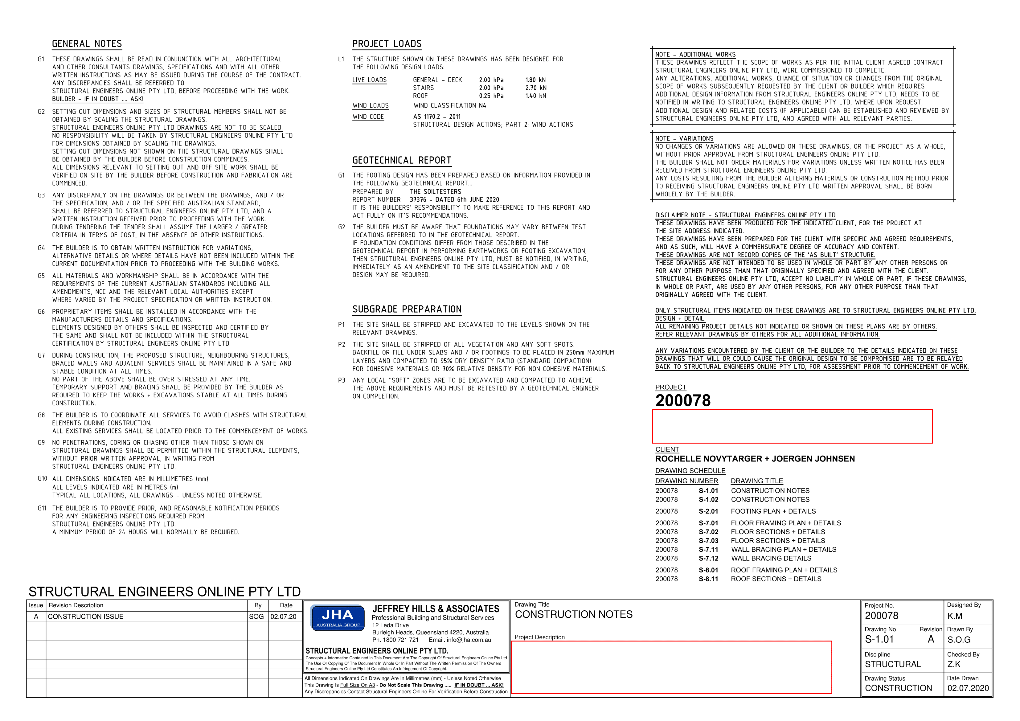
Refer to the title block of the construction plan and locate the ‘date drawn’ field or a similar field where the date of creation is stated10. Ask the appropriate personnel if the plans created on the date specified in the sheet are the most recent or current.

Step 3
Record the confirmation of the currency of the plan of the appropriate personnel in the meeting minutes.
Step 4
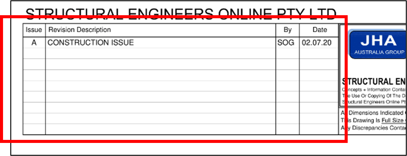
Refer to the title block of the construction plan once again and locate the ‘amendments’ field or ‘revisions’ field. Using the same structural plan sample, this can be found at the lower left-hand corner of the sheet. Refer to the image below.10
Step 5
Ask the appropriate personnel if all the amendments specified are the most recent ones. In other words, confirm if all recent amendments have been stated in the amendments field to ensure that no amendments were left out or disregarded.
Step 6
Confirm if all amendments specified in the amendments field have been incorporated into the current plan.
Step 7
Record the confirmation of the currency of the amendments of the appropriate personnel in the meeting minutes.
Confirming the currency of specifications and amendments
Confirming the currency of specifications and amendments follows similar procedures discussed in the preceding section. However, the appropriate personnel you will be confirming with are those responsible for developing the specifications documents. Usually, they are architects, engineers, or contractors. Regardless, this information is stated in the preliminary pages of the specifications documents for easy reference.
The steps in confirming the currency of specifications and amendments are as follows:
Step 1
Meet with the appropriate personnel who had developed the specifications documents. You may use the following communication methods for the meeting:
- Face-to-face meeting
- Phone call
- Online meeting with or without screen-share
Step 2
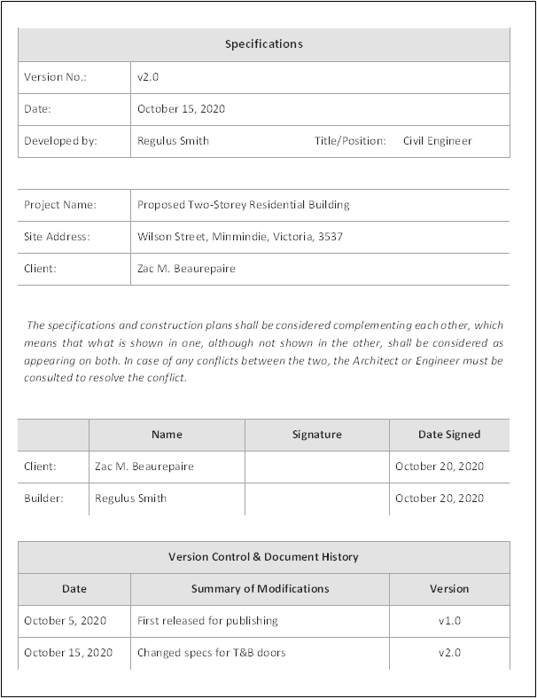
Refer to the cover page of the specifications, where you can find the preliminary details such as the project name and address and the amendments incorporated. To give you an idea, you can view a sample of the cover page below:
Step 3
Ask the appropriate personnel if the specifications created on the date specified in the sheet are the most recent or current.
Step 4
Confirm if all amendments specified in the amendments field (in the sample cover page, this is the ‘version control and document history’ field) are incorporated into the current specifications document.
Step 5
Record the confirmation of the currency of the specifications and amendments of the appropriate personnel in the meeting minutes.
Now that you have confirmed the currency of the plans, specifications, and amendments, you need to identify the types of plans and aspects of drawings specific for the intended purpose. This is important in knowing the necessary information from the plans and drawings for the building and construction project you are undertaking.
Technology used in developing plans and drawings

In identifying types of plans, two related concepts include computer-aided design (CAD) drawings and building information modelling (BIM). Both CAD and BIM are technologies used in the construction industry for the creation and management of construction drawings.
Computer-aided design drawings
Computer-aided design drawings (CAD) drawings are drawings created and modified with the use of computer software. These drawings may be two-dimensional (2D), or three-dimensional (3D) illustrations or models created and used by engineers, architects, and construction managers to create precise drawings of the building and its components.
Computer-aided design drawings are more convenient for use than hand-drawn drawings since they allow you to examine parts of the building conveniently and accurately by zooming in, measuring and overlaying as necessary. Additionally, CAD drawings can be easily modified and accessed through a database or cloud storage, allowing for faster transmission of information among involved construction personnel.
Building Information Modelling
Building Information Modelling (BIM) is a 3D model-based process that utilises tools and technologies that enable the creation and management of digital representations of physical and functional characteristics of structures, buildings and places.
BIM is used to design and document building and infrastructure designs. The model is then used for analysis to review design options and generate more visualisations that help stakeholders, for example, project clients, visualise what the building will look like after construction.
What makes it different from CAD is that BIM is used more for real-time collaboration among different construction personnel. BIM allows construction personnel from different areas of the construction (e.g. structural, architectural, plumbing, etc.) to point out areas of conflict and any discrepancies present in the model. Using the BIM model, they can easily brainstorm and make the necessary changes to resolve identified conflicts before construction begins.
Types of plans
In a building project, different types of plans serve different purposes and contain specific technical details related to each area of construction.
Concept drawings and sketches

Concept drawings and sketches are simple 3D drawings that are drawn free-hand or with sketching software. In other words, creating concept drawing and sketches do not require the use of advanced drawing software such as computer-aided design (CAD).
Concept drawings and sketches can be made using pen and paper to emphasise main building principles and features satisfactorily. They can be used to present preliminary ideas regarding the building project quickly. Since these drawings are generally simple, they can also further explore more ideas and quickly incorporate them into the drawing.
Concepts related to these types of drawings are sketch plans and presentation drawings.
Sketch plans are scaled drawings that show the true proportions of the building and its components. It is more detailed than simple sketches but not as detailed as the final drawings. However, sketch plans provide a realistic picture of how a building and its components will look.
Presentation drawings are 2D or 3D drawings used to formally present a project to an audience, whether to clients or other industry professionals. They are usually created using computer-aided design and highlight the building features through elevations and sections of the building, 3D isometric and perspective views, and landscaping. Presentation drawings may include realistic renderings and animation to capture the look and feel of the building.
Architectural plans
Architectural plans are drawings used to acquire details about the architectural aspects of a building and how architectural elements are integrated into the building. Generally, the forms of representation of the information contained in architectural plans include, but are not limited to, the following:
- Architectural floor plan
- Site plan
- Elevations
- Sections
- Perspectives
- Details
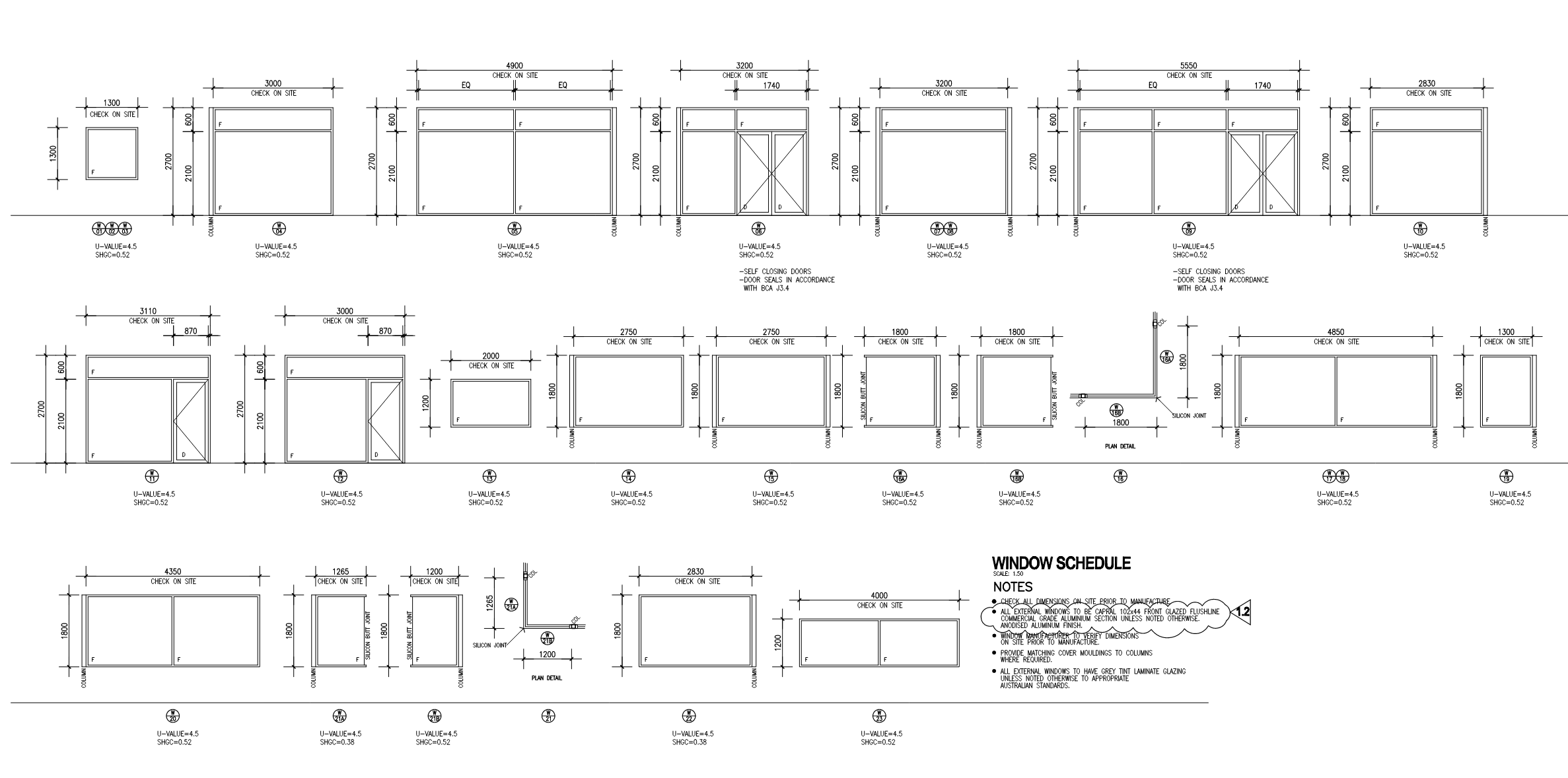
- Schedule of windows and doors
For example, if you intend to acquire details of windows and doors used for toilets and bathrooms, you can refer to the schedule of windows and doors. This will give you an idea of the specifications, such as the dimensions, type of material, and configuration.
Structural plans
Structural plans are drawings used to acquire information about the structural aspects of the building, such as specifications of load-carrying members, dimensions of structural components, etc. While architectural plans are concerned with information regarding the building's aesthetic, function, and general feel, structural plans focus on elements that make the building strong and stable against expected external forces.
Generally, structural plans include but are not limited to the following details:
- Structural floor plan
- Foundation plan
- Elevations
- Section
- Detail views
- Connection details
- Schedule of materials (e.g. the schedule of beams, schedule of footing, etc.)
For example, if you intend to know how footing elements are laid out in the construction site, you can simply refer to the foundation plan. The foundation plan shows how footings are positioned and contains information such as the dimensions of footing elements and their distances from each other.
Civil plans

Civil plans are drawings that are typically provided by Civil Engineers and show an overview of all the construction site elements, including stormwater management, road and other paved areas. They also show how these integrate into each other during the construction phase.
Like architectural plans, civil plans contain the contours of the landscape. You can refer to civil plans if you intend to identify a change in the level of a footing element at a specific area on the site.
Mechanical plans
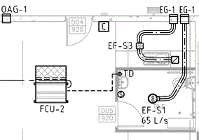
Mechanical plans are drawings that contain the specifications related to mechanical equipment and processes, such as heating, cooling, ventilation, and transportation. Examples of mechanical equipment include heating, ventilation and air-conditioning systems (HVAC), lifts, escalators, and ducting.
Generally, mechanical plans include, but are not limited to, the following details:
- Size, type, and layout of ducting
- HVAC layout
- Thermostat type and location
- Heat-loss and heat-gain calculations
One example where you can use mechanical plans as a reference is when you need to locate where the different types of mechanical equipment are placed in the building. In addition to that, you can also trace the layout of the necessary ducting in the building.
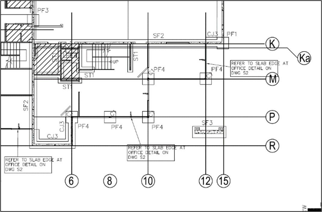
Electrical plans
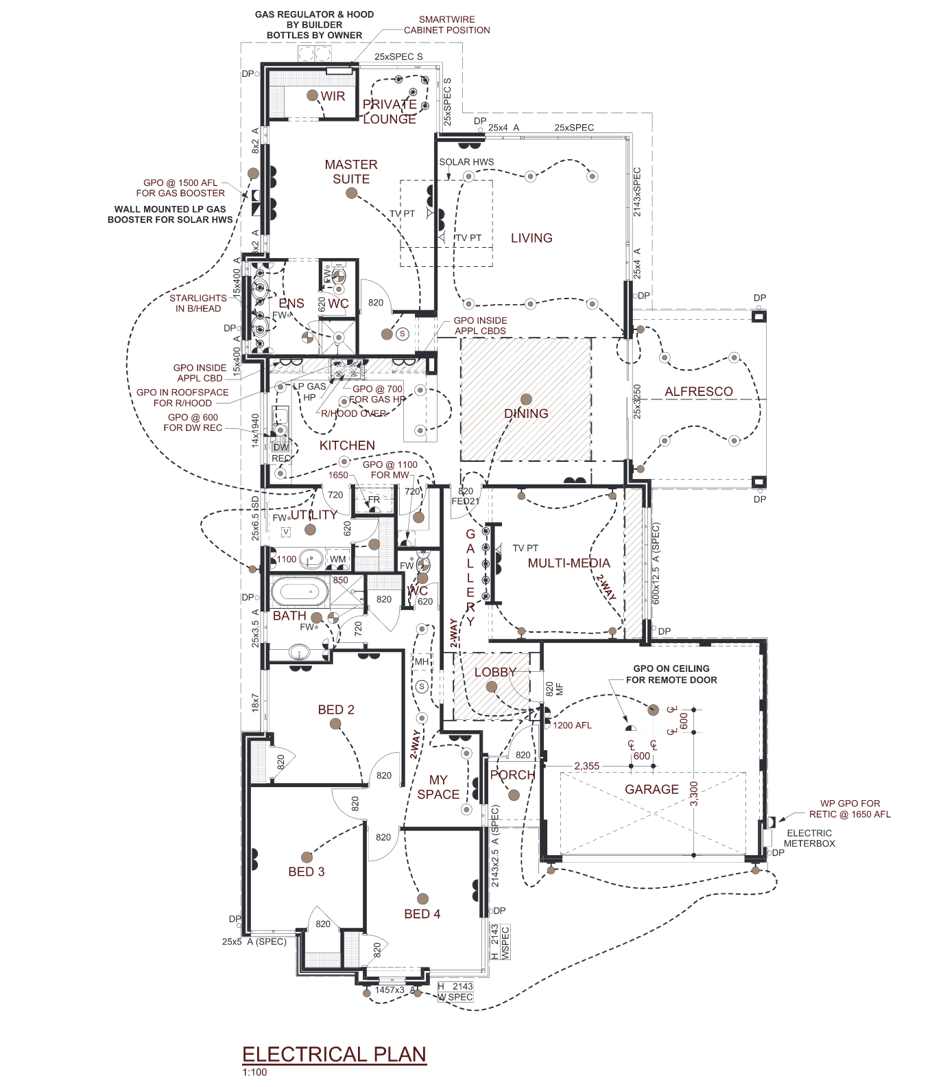
Electrical plans are drawings used to acquire information about building elements related to electrical systems or circuits, such as power, lighting, and communication. Details contained in these plans include, but are not limited to, the following:
- Wiring layout for power
- Wiring layout for lighting
- Location of panels and switches
- Schedule of loads
You can use electrical plans as a reference in instances where you need to quantify the number of lights in a specific area (e.g. kitchen, living room, patio). You can also use electrical plans to identify the type of lighting to be used in a specific area.
Plumbing and draining plans
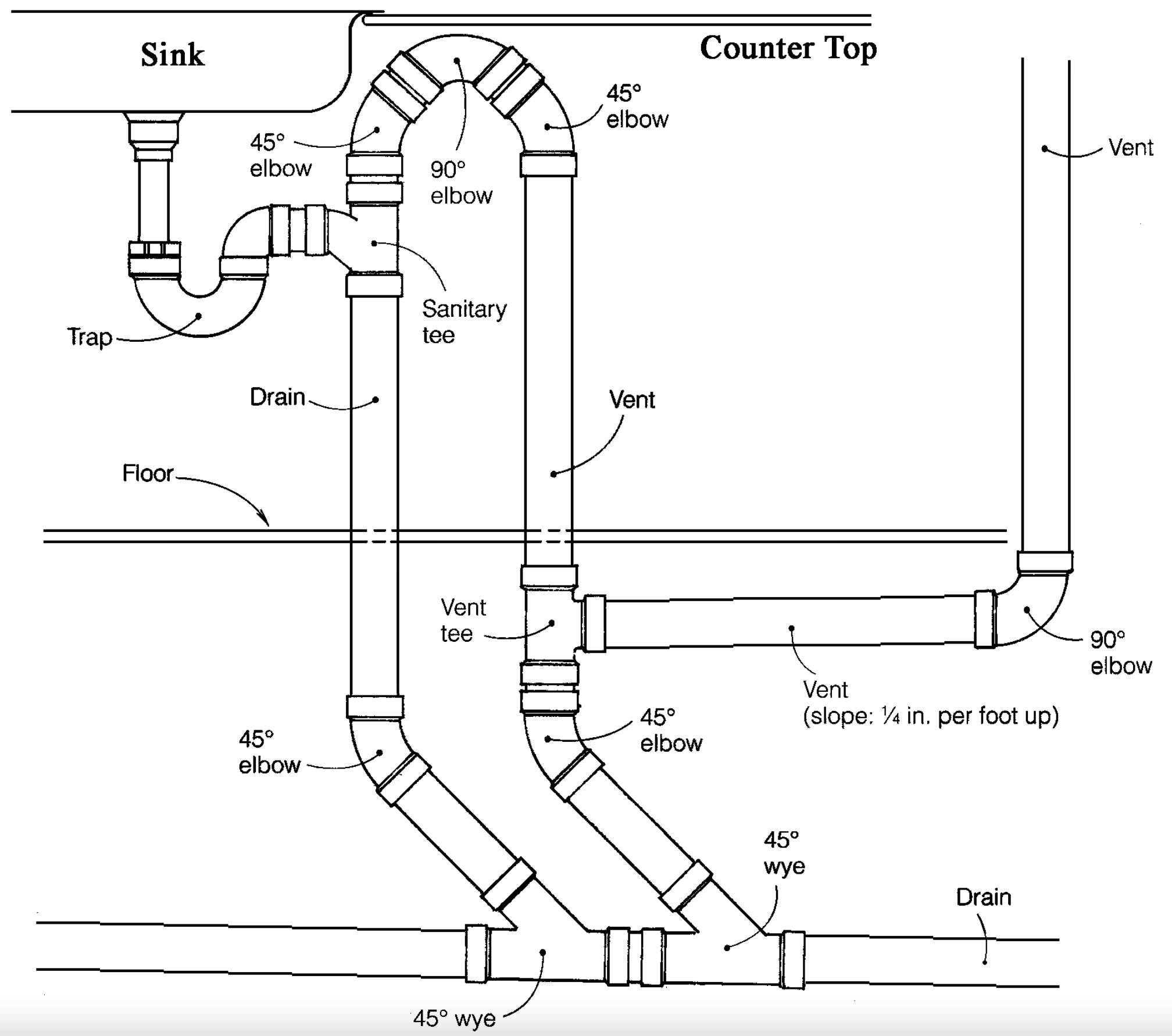
Plumbing and draining plans, also known as plumbing and drainage plans, are drawings that provide visual representations of elements related to plumbing systems. These plans can be used as a guide in the installation of water supply and drainage components such as pipes, fixtures, valves, sanitaryware, etc.
One primary concern of plumbing and drainage plans is the water supply system. Details related to water supply system include but are not limited to the following:
- Sizes of water supply pipes
- Pump capacity
- Quantity of pumps
- The layout of piping for potable and non-potable water.
The other primary concern of plumbing and drainage plans is the drainage system. Details related to the drainage system include but are not limited to the following:
- Manholes/Inspection chambers (or pits/sumps)
- Septic tank layout
- Location of sanitary fixtures
- The slope of drainage pipes
You can use plumbing and drainage plans as a reference in identifying the sizes and locations of downspouts used in draining rainwater from roofs.
Each pipeline construction project is unique. Pipelines must comply with AS 2885: The Standard for Gas and Liquid Petroleum Pipelines. AS 2885 is considered to be ‘single and sufficient’ for design, construction, maintenance and operations of petroleum pipelines because it is comprehensive in the matters that need to be covered by pipeline technical regulation and there is no need for the State technical regulators to make further or additional technical regulations. In NSW, for instance, under the Pipeline Regulations 2013, a licensee must implement a pipeline management system that relates to the pipeline operated under the licence and is in accordance with the relevant provisions of AS 2885. You must always familiarise yourself with the regulations and licensee responsibilities relevant to your state/territory.
Utilities and services plans and specifications

Utilities and services plans are drawings that contain information about construction site utilities and services. On the one hand, the utilities plan is concerned with providing information regarding the supply for electricity and water, gas supply, sewage, and other considerations necessary for the construction phase. On the other hand, the services plan is concerned with systems necessary for the smooth flow of construction operations, including fire safety detection and protection, lighting, and security and alarms.
In general, utilities and services specifications are important textual descriptions that supplement the drawings contained in the utilities and services plans.
Utilities specifications are important since they contain information about utilities that cannot be shown in the utilities drawings. It provides supplementary in-depth information about the drawings in the utilities plans and the utilities in general.
Similarly, services specifications are important since they contain information about services that cannot be shown in the services drawings. It provides supplementary in-depth information about the drawings in the services plans and the services in general.
Aspects of drawings
Aspects of drawings are drawing elements that are typically found in construction plans. They are also known as parts of a plan.

There are five (5) aspects of drawings:
Site plan
A site plan is a drawing that provides an overview of the entire property. It shows all site elements to be considered in the construction of a building and gives an idea of the entire scope of work involved in the project. Additionally, a site plan is usually drawn at a smaller scale to ensure that all the required information is placed in the drawing sheet. An example of a site plan1 can be seen below.
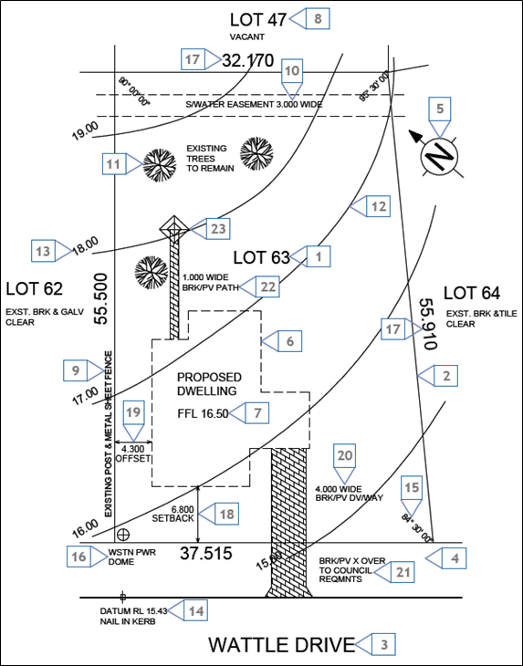
This aspect of drawing can be used for purposes such as identifying adjacent roads, identifying the location of the project site, determining structures to be retained or demolished, and determining the building layout and orientation, access, falls, etc.
Below are the key features of a site plan. Note that the numbers below correspond with the labels in the sample site plan shown above.
- Block identification – refers to the block number of the land.
- Boundary – refers to an imaginary line that defines the block of land, with corners marked by wooden pegs.
- Road identification – refers to the names of roads adjacent to the property.
- Verge – refers to the portion of land between the block and the road, which usually has services running beneath it. Since this is not part of the block, it must not be built on or modified in any way.
- North point – shows where the north direction is. This dictates the orientation of the building on the site during the design process.
- Proposed building – shows the outline and location of the building to be constructed.
- Finished floor level – refers to the finished floor level of the building to be constructed.
- Adjacent properties – refers to the lot numbers of adjacent blocks of land.
- Existing fences – refers to fences already existing on the block.
- Easement – refers to a portion of land wherein another party exercises a legal right (e.g. council has the right to use a portion of land solely for stormwater lines)
- Existing trees – refers to the trees that exist in the site. They are specified as site elements to be retained in the sample site plan.
- Contour lines –refers to imaginary lines which describe the profile of the land through the indication of horizontal cut lines of the terrain. In the site map sample shown, the block is sloping down from north to south.
- Contour level – refers to the ‘reduced level’ of the contour. In the site map sample show, the contour lines are in one-metre intervals.
- Datum – refers to a reference point on or near the block upon which all site elevations are measured from.
- Angle of boundary intersection – refers to the angle at which the boundaries meet.
- Location of power connection – shows where electrical connections will be made.
- Boundary length – refers to the length of the boundaries of the block.
- Setbacks – refers to the distance from the front, rear or side boundaries to the nearest part of the building.
- Offset (side setback) – refers to the distance from the side boundaries to the nearest part of the building.
- Driveway – refers to the location and width of the driveway.
- Crossover – refers to the continuation of the driveway across the verge.
- Path – refers to any paving works included in the contract.
- Clothes hoist – refers to the positioning of the clothes hoist in the site.
Floor plan
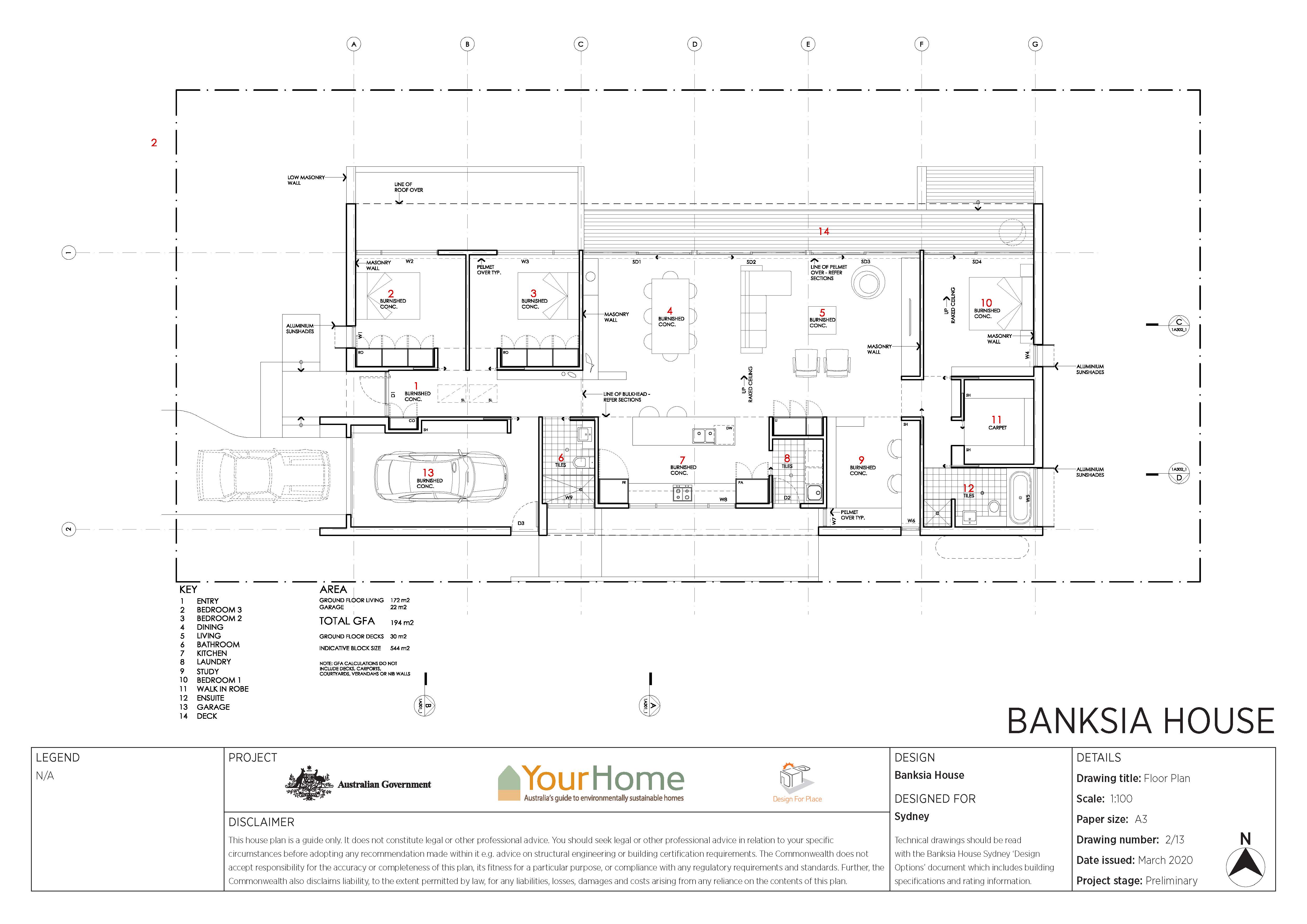
A floor plan is a graphical representation of a building section’s top view. It shows the arrangement of elements such as walls, columns, doors, and windows and defines the limits of the building’s different spaces.
Refer to the Banksia House floor plan above and identify the different furniture and appliances for the building. Additionally, you can use it to identify the function of the different building spaces and their dimensions. Other types of information that can be acquired include, but are not limited to, the following:
- Location of appliances
- Layout of walls
- Width of doors and windows
- Width of stairs
- Arrangement of furniture
Elevations
Elevations are views that show the horizontal projection of the building as seen from outside. In other words, it shows what the building façade looks like at the front (front view), back (rear view), and sides (right side and left side view). This allows one to analyse the relationships of components found only on the building exterior (e.g. wall finish). Other details obtained from elevation views include the roof’s eave and ridge height, and the proposed materials and finishes.
Refer to the following images to see what elevations look like:

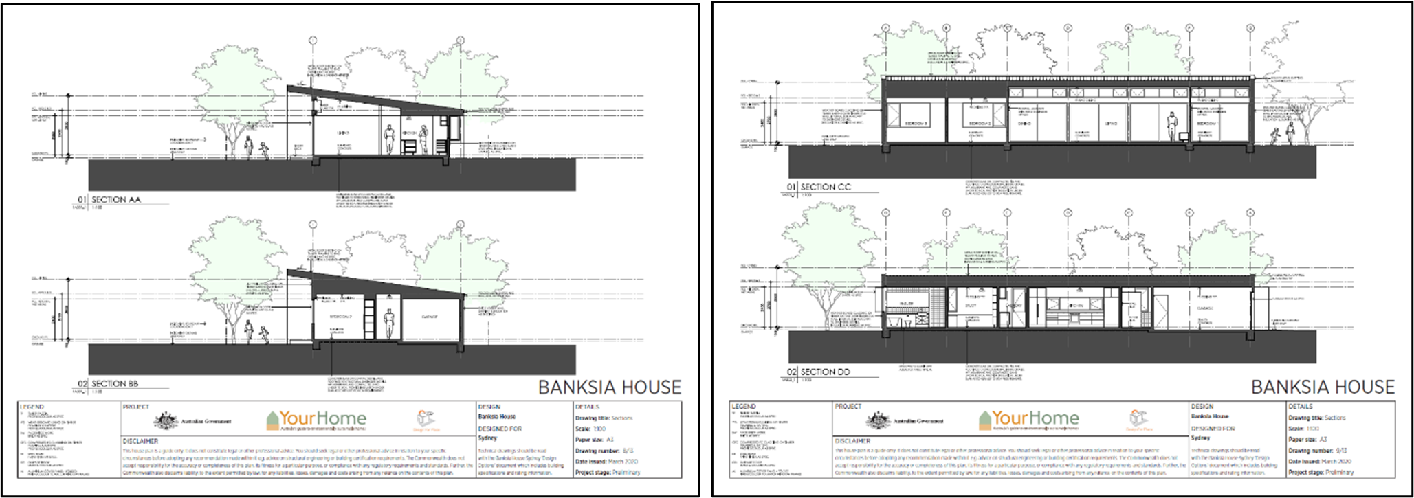
Sections
Sections show what a structure looks like with respect to an imaginary vertical plane that cuts through it. This imaginary cutting plane allows one to see through the structure's interior which is otherwise concealed by the exterior walls.
Since section views allow one to look at the building interior, one can analyse the relationships and integration of interior building elements. Additionally, section views will enable the identification of any variations in a floor level. Other details which can be obtained from section views include but are not limited to the following:
- Floor-to-ceiling height
- Dimensions of doors, windows, and other openings
- Dimensions of fixtures, furniture, and equipment
Refer to the following images to see what elevations look like:
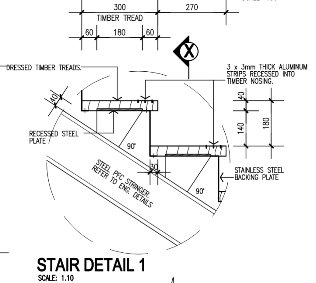
Details
Generally, plans are drawn in the appropriate scale for a drawing sheet to cover the necessary information. However, there are instances when one needs to look deeper into a particular section or component of a building to examine it. This is when detail drawings come into play.
For example, if you want to know the width and thickness of the stair tread and the measurement of the stair rise, you would look at the stair detail drawings. An exampe of a stair drawing is shown below:
Drawing projections
Drawing projections are drawings that show different views of how 3D objects look in 2D. These drawings are used in creating the site plan, floor plan, elevations, sections, and details discussed previously. These are:
Isometric Drawings

Isometric drawings are 3D drawings on a 2D surface where the same scale is used for all axes. Additionally, these drawings are set out using 30-degree angles. Isometric drawings are used for the purpose of viewing a 3D image with the corresponding scaled dimensions since these drawings represent a non-distorted version of an object.
Oblique Drawings
Oblique drawings are the 2D projection of 3D drawings that represent an object accurately by showing the true shape and form of the object based on the observer's point of view. This is typically used to directly look at certain features of an object based on the desired view of the viewer.
The image below shows examples of oblique drawings. As you can see, oblique projections have one vertical axis and one horizontal axis (forming a 90° angle with each other), with the third axis forming 30°, 45°, and 60°, respectively, with the horizontal axis. Note that the third axis can form an angle from 30° to 60° with the horizontal axis.

Orthographic Drawings
Orthographic drawings are drawings wherein 3D images are presented in 2D, in which three views are produced (e.g. top view, front view, and side view). These can be used for the purpose of examining how building spaces or elements look in a top, front, or side view, and identifying relationships among building elements based on the view. These drawings are very important in the planning stage of construction. Floor plan and elevation views, which were discussed previously, are both examples of orthographic drawings. The image shows an example of orthographic drawings.

Perspective Drawings

Perspective drawings are 3D drawings that show an approximate representation of an object as the eye perceives it. These drawings are typically used to give a realistic representation of the building. The image shown above is an example of a perspective drawing.
Confirming whether details on plans comply with the specifications is essential when dealing with a building project. While plans contain the necessary drawings, specifications contain the textual technical descriptions of these drawings and other information which cannot be expressed clearly in the drawings. In other words, the specifications state the detail of work necessary to complete the building project and the standards that all work must comply with during the whole construction phase. These standards include suitable materials, installation procedures, limitations, and types of products to be used for certain building elements.
Additionally, the specifications are part of the larger legal document referred to as the construction contract. Not following the contract can result in a breach of contract, which can lead to consequences for all parties involved. Therefore, to prevent this from happening, any discrepancies regarding the details on the plans and specifications must be pointed out and clarified beforehand.

In confirming the compliance of the details on plans with the specifications, you must:
- Outline the critical points stated in the construction specifications, including:
- Product details
- Material details
- Dimensions
- Installation/erection procedures
- Equipment to be used
- Limitations/constraint
As an example regarding material details, the specifications may state that the entrance to the house is to be made of powder coat commercial aluminium frame. There are also instances when the specifications say, ‘As per engineer’s drawings.’ In this case, the drawings referred to are considered to have fully captured the specifications.
-
Before you begin checking the details on the plans, make sure to take note of the currency of the construction plans. Note down the publication date and version.
- Indicate whether the details in the construction plans achieve compliance for the critical points mentioned, namely:
- Product details
- Material details
- Dimensions
- Installation/erection procedures
- Equipment to be used
- Limitations/constraints
Going back to the example in step one, the specifications may state that the entrance to the house is to be made of powder-coated commercial aluminium frame. You must then check if this is the case with the construction plans. You can search the architectural plans and examine the floor plans, detail views of doors and the door schedule and see if the drawings are exactly as the description in the specifications.
In cases where you find any portion of the drawings which do not comply with the specifications, you must note them down and state why these drawings did not comply with the specifications (i.e. the reason for non-compliance). For example, the plans containing the main house entrance could identify standard metal door frames instead of powder coated commercial aluminium frame stated in the specifications. It is important to note these down to be raised to the relevant construction personnel for clarification.