What we're covering:
- electrical cables
- cords
- circular and flat cables
Legislation
- Before we begin it is important to be familiar with and to comply with the relevant legislation for this section. The selection and installation of wiring systems must be performed according to the:
- Electricity (Safety) Regulations 2010.
- Health and Safety at Work Act 2015.
- AS/NZS 3000:2018, Electrical installations (known as the Australian/New Zealand Wiring Rules), including Amendment 1.
Which section of the Wiring Rules outlines the requirements for the selection and installation of wiring systems?
- AS/NZS 3008.1.2:2017 Electrical installations – Selection of cables – Cables for alternating voltages up to and including 0.6/1 kV (at 50 Hz) – Typical NZ conditions (nominal ambient air and soil temperatures are 30°C and 15°C, respectively).
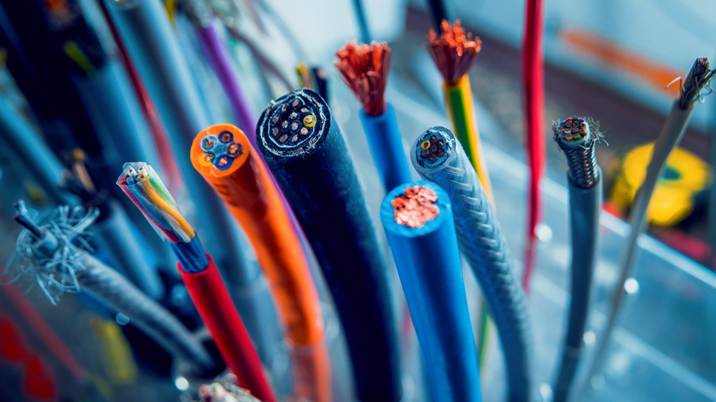
Cords and cables
Cords and cables both transmit electrical power.
AS/NZS 3000 1.4.20 defines a flexible cable as – “A cable; the conductors, insulation and covering of which afford flexibility.”
AS/NZS 3000 1.4.36 defines a flexible cord is defined as a flexible cable in which:
- The individual wire strands are smaller than 0.31mm diameter.
- No conductor exceeds 4mm2 cross-sectional area. (Once the CSA exceeds 4mm2 it is referred to as a flexible cable.)
- The sheathing contains no more than 5 cores.
A flexible cord consists of very small individual strands of copper wire, making up a flexible conductor core which is then insulated. Each core in the cord is the same size.

- Up to 5 cores are combined and a sheath of insulation is put around the outside.
- The thickness of the sheath determines the ‘duty’ type of the cord, i.e., light duty, ordinary duty or heavy duty.
- The most common types of flexible cord used for portable electrical appliances, range in size from 0.75 mm2 to 1.5 mm2 with two or three sheathed cores.
The wire ‘size’ is the cross-sectional area of the wire, which is the area of the circular cross-section of the wire, in mm². If a flexible cord has a total cross-sectional area (CSA) of 0.75 mm2, it would be referred to as 0.75 mm2 flex.

For circular cross sectional area conductors, use π r2 to calculate cross sectional area.
Cords may also be described by the number of strands and diameter of each strand in each core. A common type of 0.75 mm2 flexible cord could be referred to as 24/0.20 (24 strands, each 0.2mm in diameter).
Try out the maths! The cross-section area of bunched wires can be calculated as:
A = n d2 π /4
where: n = number of wires and d = single wire diameter (mm)
Note – Cables above 1 mm2 must have stranded conductors according to NZACP 51:2004.
Activity
Check your understanding by answering the questions in the worksheet about cables before proceeding. Email your answers to your tutor.
Circular cables and flat cables
The cable system is expected to last the life of the equipment, so it is important to choose cable that maximises durability and longevity, while meeting other requirements. Flat and round cables have significant design differences that make them suited to different applications.
Circular Cables
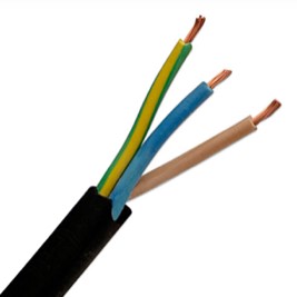
Round or circular cables contain one or more conductors, covered with insulation and packed with protective material giving the cable a rounded, cylindrical shape.
Although less flexible than flat cables, round cables can bend along any axis, making them suitable for applications that require extensive bending and twisting in long cable runs, especially raceways or conduits.
Round cables are also more suited to applications requiring protection against environmental factors such as:
- Rail transportation – harsh weather and constant motion.
- Material handling – heavy loads and vibrations.
- Waste processing operations – wet environment with heavy-duty moving parts.
- Power distribution systems in high-rise buildings such as office buildings, hotels, hospitals, shopping malls, etc.
- Lighting systems for highways, bridges, and tunnels.
Flat Cables
As the name suggests, these cables have a flatter design. Conductors are individually encapsulated, carefully arranged in a straight line at precise intervals and surrounded by insulation. Unlike round cables, flat cables do not usually have layers of fillers and shielding, making them relatively compact and lightweight, making them less prone to wiring errors and cheaper to manufacture.

Flat cable wire bends easily in only two directions, making them best suited for rolling flex, since this movement is in one linear axis.
The heat dissipation of flat cables is superior to round cables because of their higher surface-area-to-volume ratio. Consequently, flat cables handle higher temperature rise and current levels per conductor cross-section.
Flat cables are suited to applications requiring flexibility or with tighter space requirements. They save on installation space and cost, and their bending radius is smaller than that of round cables with the same number of core wires.

Their applications include:
- Robotics applications involving highly complex designs in very tiny spaces.
- Telecommunications - for navigating cramped areas and saving space.
- Overhead cranes with space limitations and the necessity of continual flexing.
- Lifting equipment, cable tracks, trolleys, transmission machinery, elevators, telescopic machinery, and other mobile electrical power transmission lines and control, lighting, communication channels in special places, and they can also be used in enclosed indoor environments.
Activity
Complete the table in this worksheet comparing flat and circular cables. (The first feature has been done for you.)

What we're covering:
- construction and configuration
- TPS cables
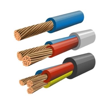
An electrical cable is used for the transmission and distribution of electrical energy. Circular cables consist of the following parts:
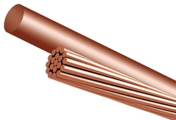
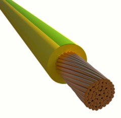
- Conductor(s): channel the flow of electricity and are made from either plain or tinned copper, or solid or stranded aluminium. Solid conductors consist of a single piece of metal wire, while stranded conductors are composed of several thinner wires twisted into a bundle. The bundled strands can be configured into a variety of geometric arrangements to meet specific design requirements for any device or application.
- Insulation: covers the conductor to prevent current leakage. The two main types of insulators are thermoplastics (e.g., polyvinyl chloride, PVC), and thermosetting plastics (butyl rubber, ethylene propylene).
- Auxiliary elements: protect the cable and extend its lifespan. Includes metal shields (screens) to isolate signals that pass through the interior of the cable from possible external interference; mechanical armour to protect the cable against damage and in some cases provide earthing; a fill layer surrounding the conductors to maintain the circular cross-section. These will vary depending on the situation the cable will be used for. (More on this later.)
- Outer sheath: provides external mechanical protection against damage from moisture, corrosion, dirt, sun, temperature, fire, external aggression etc.

Activity
Complete the following table by matching these three common stranded wire arrangements of conductors, to their correct description and diagram.
*Note - concentrically laid cables can be bundled in several ways, decreasing their overall size. For a compressed concentric layout, the conductor is assembled and pulled through a die to bring the strands closer together, whereas a compact concentric layout shapes the strands into trapezoids before being bundled together to remove as much empty space as possible.
A size comparison is shown here:

Manufacturer's information
Cable manufacturers provide information about their cables such as operating voltages, temperature ratings and conductor type and size. Further cable specifications, such as those below, can be found in the manufacturer’s technical data publications:
- Overall cable dimensions.
- Resistance to direct sunlight, UV, chemicals, water, and fire
- Weight of cable per unit of length
- Mechanical properties of insulating materials.
- Chemicals released when combusted
- Application
- Approvals
- Installation conditions.
Different manufacturer’s specification tables vary in detail, so it is important that you use the appropriate tables for the cable you are using. Two examples can be found here of specifications for Flat TPS cable. Read these, focusing on the information provided in each case.
Activity
Find 3 similarities and 3 differences for the two TPS cables and list these in the table provided in this worksheet.
Activity
- Cable manufacturers will often include the Minimum Bending Radius for cables in the specifications. (Refer to the Prismian cable example.) Research this term.
- Look up the term Minimum Bending Radius and explain on a piece of paper why it is important in cable selection. You should bring your findings to class and discuss with your tutor.

What we're covering:
- cord colours
You must follow the correct wiring colour codes during installations. Refer to Section 3.8 of the AS/NZS 3000:2018 which specifies the correct conductor colours to be used for installation wiring.
For electrical safety, the wiring colour codes for AC and DC wires, as well as single phase and three phase systems, are critical. Compliance not only saves you time by ensuring easy maintenance and troubleshooting; it protects those who are working on, or coming in contact with, the installation.
You are probably aware that every country has its own electrical code for cable and wire installation and electricity distribution. The US and Canada follow the NEC “National Electrical Codes” and most of Europe, including the UK, follow the IEC “International Electrotechnical Commission” codes. Extra care must be taken when connecting imported equipment that does not use AS/NZS conductor colours!
In New Zealand we follow the Australia & New Zealand Wiring Colour Codes for single phase and three phase power circuits. The live wire is brown, the neutral is blue, and the earth is green and yellow. Because wire colour codes have changed throughout time, this may not be the case for every electrical system – you may come across earlier systems that have different colours.
These updated conductor installation colours for flexible cords, flexible cables and equipment wiring are now in keeping with typical European (IEC) practices.
The comparison of conductor insulation colours of multiphase cables manufactured to current AS/NZS Standards, as well as equipment manufactured to typical European practices, is shown below:

Important
When flexible cords or cables are used for installation wiring purposes (not extension or appliance cords), black and light blue are not to be used as active conductors.
Activity
Recap – match the wire to its correct colour and role.
Activity
Refer to AS/NZS 3000:2018 Section 3.8 to answer the questions on this worksheet.
Activity
Cable insulation materials may be categorised as either Thermoplastic or Thermosetting. Research the important characteristics of each material and how these affect their insulating properties.
- Thermoplastic materials are…
- The advantage(s) of using thermoplastic insulation is…
- Two examples of thermoplastic insulators are…
- Thermoset materials are…
- The advantage(s) of using thermoset insulation is…
- Two examples of thermoset insulators are…

What we're covering:
- TPS cables - flat and circular
The NZECP 51:2004 Section 3 Table 2 provides guidelines for selecting and installing cables. Namely - Tough plastic sheathed (TPS) cable must be used for both the mains cable and installation wiring, while polyvinyl chloride (PVC) insulated conduit wire must be used for main earth or main equipotential wiring in NZ.
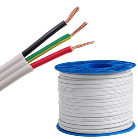
Tough Plastic Sheathed Cable
TPS cable consists of an outer sheath of PVC insulation (usually white for flat TPS and black for circular TPS) and one or more inner coloured thermoplastic sheaths enclosing a copper core or cores - either single or multistrand. It is double insulated since are two layers of insulation material protecting the conductors.
Flat TPS is used for fixed wiring where there is less chance of mechanical damage e.g., lighting, power outlets, appliances, and heating, ventilation and air conditioning (HVAC) units. It is available in several conductor configurations: single, twin, twin and earth, three and earth, and four and earth (the latter two are used for three-phase supply). ‘2 + E’ is the quick way to write twin and earth cable wire.
For instance, the typical wiring requirements of a range/oven are:
- minimum 2 + 6mm2 TPS cable
- protection by a 32-40A MCB in the distribution board.
Circular TPS cable is suitable for fixed installation in industrial installations. It has a hard PVC sheath making it more robust than flat TPS and easier to run.
Flat cables have greater surface-to-volume ratio than their round cable counterparts, consequently having higher efficiency in dissipating heat. This allows a higher current level for a given temperature rise and conductor cross-section.
Standard V-75 or V-90 TPS, (with maximum operating temperatures of 75°C and 90°C respectively), should not be used below 0°C as the insulation becomes brittle and will shatter. These cables must also be protected from external influences such as UV radiation, chemicals, or oils.
Contact with some building materials such as polystyrene, polyurethane, and bituminised building papers may also damage PVC insulation. To avoid this problem either use a cable with a migration-resistant plasticiser as shown here or prevent the cable contacting the material altogether.
Conduit wire refers to single core insulated cables without a sheath. It comes in a range of sizes and is often used for wiring in enclosures such as internal switchboard wiring.
Conduit wire is often installed with extra protection, such as conduit*, since the conductor is only protected by a single layer of polyvinylchloride (PVC) insulation.
*An electrical conduit is a tube in which electrical wires are housed for added protection. When wire is to be installed in conduit, there may be restrictions due to size, temperature, explosion considerations and other factors.
Activity
Research the following types of cable insulation. In each case provide a brief description of the material; its insulating properties; and its application. You can write your ideas on this worksheet.

What we're covering:
- External influences: temperature, heat, moisture, foreign bodies, corrosion, mechanical damage
External Influences
(Havire, 2019)The system of cables used for the transmission of electricity is typically outdoor and subjected to harsh environmental factors which means cables require protection to guarantee proper functioning over a prolonged period and safety. The factors that affect cables can be categorised into ‘Thermal’ and ‘External Influences’.
External influences are any influences external to the cables which can affect the safe operation of the cable and its design. In the previous SDL task, you compared aerial conductors - prone to environmental attack from lightning and windstorms, with underground cables which are more susceptible to ground water infiltration and mechanical damage. External influences include:
- Ambient temperature.
- External heat sources.
- Moisture (rain, humidity, water accumulation).
- Solid foreign bodies.
- Corrosive or polluting substances.
- Mechanical damage and stresses.
- Fauna and flora (animals and plants).
- Hazardous areas.
- Thermal insulation.
- Solar radiation.

Ambient temperature
Refers to the temperature of air or any other medium where the cables are installed. Hot and cold temperatures are some of the most critical factors related to cable performance. A rise in the temperature of the conductor increases its resistance and decreases its current capacity. Deterioration of cable insulation is accelerated by hot temperatures - in extreme cases the insulation may melt causing electrocution and fires.
Cold temperatures also have adverse effects on wiring and cables. As cable conductors lose heat, they become less effective. Low temperatures also cause most non-metallic and composite insulating materials to become brittle and inflexible, to the point of breaking.
According to AS/NZS 3000, wiring systems must be selected and installed so as to be suitable for the highest and lowest local ambient temperatures.
Activity
Where current-carrying capacity is selected in accordance with AS/NZS 3008: Part 1.2, what is the reference ambient temperature for cables? Write your answers in this worksheet, which you will use for the next three activities as well.
External heat source
High ambient temperatures are unavoidable in certain situations, for instance commercial kitchens, blast furnaces, coke ovens, and cement kilns. Proximity to adjacent cables will also increase the temperature of the cable.

Activity
With reference to AS/NZS3000 Section 3.3, list four steps you could take to protect wiring systems against the effects of heat from external sources. Write your answers on the same worksheet that you downloaded for the previous activity.
Moisture (rain, humidity, water accumulation)
When moisture comes into contact with electrical wiring, it can cause corrosion, short circuits, earth leakages, shocks, and even fires. Moisture may ingress a cable radially, i.e., by permeation through the protective layers (sheaths) or through any breach of these sheaths (mechanical damage), or longitudinally where water enters the cable through ineffective end capping or poorly made joints or terminations.

Solid foreign bodies
Wiring systems should be selected and installed so as to minimise the entry of solid foreign bodies during installation, use and maintenance.
Activity
What are some examples of solid foreign bodies that could enter an installation system? Write your answer on the same worksheet you downloaded for the previous activity.
Corrosive or polluting substances
Corrosion is the deterioration of metals through the combined actions of oxygen, water, other metals and salts. It is a problem for two reasons – the loss of material and additional resistance, resulting in heat development and ultimately in failure.
Aluminium oxidises readily in air forming a hard outer layer of electrically insulating oxide. Copper oxidises to a much lesser extent than aluminium and its oxide is conductive, although not as conductive as the base metal.
Galvanic corrosion occurs when two electrochemically different metals, in contact with each other, are exposed to an electrolyte. Aluminium is particularly susceptible to galvanic corrosion since it is a relatively reactive metal in the galvanic series. The photographs illustrate aluminium connectors on copper conductor before testing (top) and after 2000 hours of environment testing (bottom).

Activity
According to AS/NZS3000 Section 3.3, what precaution should be taken to reduce the possibility of galvanic corrosion in an installation? Write your answers on the same worksheet that you downloaded for the previous activity.
Chemicals coming into contact with cables may also cause corrosion. The cable jacket can swell or harden, eventually cracking to expose the conductors. Chemicals and pollutants include oils (found in machines for lubrication and cutting), acids, cleaning agents, butanone (in degreasers), ammonia and nitrates (used in agriculture), salt (coastal regions), hydrogen sulphide (geothermal regions and forest products processing)
Ground water, or accumulated water in a cable trench that contains corrosive substances may result in corrosion. Similarly, the burning of fossil fuels releases acidic compounds into the air, causing corrosion to aerial and exposed cables.
Mechanical damage and stresses (including vibration)
Mechanical damage to cables can be due to breaks and defects of sheath material, mechanical punctures by people or machines, or cracks due to sharp bending or vibration. Damage may occur during installation by using excessive pulling tension and/or exceeding the minimum bending radius; during maintenance or installation work; or during construction when earth moving equipment severs the cable.

Once mechanical damage occurs in the cable sheath, moisture ingress will cause slow deterioration of insulation material and eventual failure of the cable.
Activity
- What factors should be considered when selecting the appropriate cable for a specific application to minimize the risk of mechanical damage to the cable insulation, sheathing, and connections? Provide at least four examples.
- Email your answers to your tutor.

What we're covering:
- External influences: flora and fauna, solar radiation
Fauna and flora
Fauna (animal life) includes insects, small animals and birds. Animal pests like rodents can chew through cable sheaths and the wiring inside resulting in a loss of production and extensive repair works.

Why do pests and rodents chew cable jackets? Is it a food source? The answer may surprise you: find out in this article 'Rats will devour your car'.
Methods for preventing fauna problems include running cabling in hard conduit pipe and in sealed raceways or using rodent-proof protective layers of cable.
If you are wondering why pests and rodents chew cable jackets – it might be due to a chewing instinct to regulate incisor length (their teeth continue to grow over their lifetime); or an attraction to the cabling (insulating materials can be a food source for insects); or an attraction to the warmth of conductors inside cable jackets, or sensitivity to the electromagnetism of the cabling.
Flora (plant life) also pose problems for installations. In high winds, trees and their debris may blow onto power lines, causing lines to short-circuit, resulting in significant damage to electrical equipment and power cuts. Tree roots that grow around underground electricity cables and rupture insulation cause power supply failure.

Fungal growth on cable insulation may obscure wire identifications, conceal wire/cable damage, and create a health hazard. The presence of mould is an indication of moisture and its associated problems.
Thermal insulation
When a cable is run in a space containing thermal insulation, such as walls and ceilings, the operating temperature of the conductors may be exceeded, reducing the current-carrying capacity of the conductors.
According to AS/NZS 3008.1, cables passing through bulk thermal insulation must be rated for current-carrying capacity depending on length of cable passing through the insulation.

Activity
Drag and drop the correct rating for each cable length.
Solar radiation
For any cable exposed to direct sunlight the following effects must be considered:
- Current rating of the cable: Cables are normally rated according to the maximum standard ambient temperature for the given installation, but ambient temperature (and rating factor) will need adjusting to account for the increase in surface temperature of the cable due to solar radiation.
Where would you find guidance on the effect of direct sunlight on the current carrying capacity of cables?
- Physical properties of the cable sheath: UV radiation causes colour fading and degradation of the cable sheath material. Cables likely to be exposed to UV light should be designed with UV resistant materials, although all polymers degrade over time. Depending on the material, it becomes:
- Tough. When exposed to mechanical stress, it cracks and crumbles.
- May change colour or become sticky and lose its insulating properties.
PVC, commonly used in sheath materials and one of the most UV resistant polymers available, eventually changes colour, becomes sticky and loses its insulating properties in the presence of UV. To reduce the effects of UV on cables, stabilisers are added to the PVC compound. The most common of these are Carbon Black and Titanium Dioxide (TiO2).
Activity
Shielding cables from the direct rays of the sun, without restricting ventilation, is the best option for minimising UV degradation. How can this be achieved during installation? Create a 'how to' poster explaining the steps that you would take to do this. Share it in the forum when you have completed it.

What we're covering:
- internal influences: circuit capacity, current capacity, resistance
Internal Influences
As well as external influences, cable selection depends on:
- Short circuit capacity of cables.
- Current carrying capacity of cables.
- Voltage drop.
- Voltage rating.
Short Circuit Capacity
A cable may be subjected to a short circuit fault current, many times greater than its normal operating current capacity. When choosing a cable, its short circuit capacity must be considered.
Normally the load keeps the current under control, but if that load is bypassed, the current is only limited by the ability of the power supply to supply current and the opposition to current flow of the circuit conductors. Hence under short circuit conditions, extremely high current will flow in a cable causing the cable to overheat.
The heat energy produced in the cable is a product of the square of the fault current and time (I2t).
The insulating material of a conductor has a maximum temperature limit it can withstand before melting. It is essential that under fault conditions, this maximum insulation temperature is not exceeded.

AS/NZS 3008 Section 5 contains tables and calculations regarding short circuit performance of cables. It is a requirement of AS/NZS 3000 that a protection device, such as a circuit breaker, must operate in the prescribed time to clear a fault. The cable needs to be able to cope until it does.
Current Carrying Capacity
All cables and flexible cords used in permanent wiring installations must operate within their design parameters. Cables and cords that do not may be damaged or cause damage to the installation (such as a fire).
The resistance of an electric cable decreases as cross-sectional area increases. A cable with a larger cross-sectional area allows a greater current flow for the same electrical pressure (voltage).
AS/NZS 3008 provides tables to assist with cable selection based on current carrying capacity in different environments. Select the column with the correct environmental conditions and move down to the design circuit current. The cell indicates which size conductor to use for the current.
Try this out for yourself using the AS/NZS 3008 tables.
Current flow in a circuit often varies. Imagine a house with eight double s ocket outlets rated at 10A (x 2 per outlet) on one circuit. It is unlikely all sixteen outlets on that circuit will have a load plugged in and all be drawing the maximum of 10A at the same time (160A in total).Wiring the circuit to cope with 160A all the time would require huge cables and switchgear and is just not necessary. AS/NZS 3000 sets out guidelines for working out a reasonable loading for circuits so you can design an installation that is reliable but not overboard on the size of gear.
The term for this is maximum demand. It is the reasonably normal maximum expected current demand on circuits or an installation. You can work out the maximum demand current and use that to choose the size of your mains cables. AS/NZS 3000 Appendix C contains information on working out maximum demand.
Activity
AS/NZS 3000 2.2.2 provides four methods of determining maximum demand current. List the four methods on this worksheet, which you will use to the complete the following activity as well.
Cable Resistance
The most important factor to consider when selecting cables is the resistance of the conductors in the cable. The resistance of a conductor is affected by its length, thickness, temperature, and the type of material it is made of.
Length of Cable
As the length of a cable or cord increases, so does the resistance of the cable. Resistance is directly proportional to length of the conductor.

- The shorter the conductor, the lower the resistance.
- The longer the conductor, the higher the resistance.
Activity
Use the data provided in the table, under the heading Graphing Activity in the worksheet you downloaded for the previous activity, to graph the relationship between conductor length (along the x-axis) and the three measurements voltage, current and resistance. You should draw 3 separate lines, with a key identifying each parameter. Answer the questions that follow.
Cross Sectional Area of Cable
Resistance is inversely proportional to the cross-sectional area of the conductor

- The greater the conductor area the lower the resistance.
- The smaller the conductor area the greater the resistance.
If the cross-sectional area of the conductor is doubled, its resistance gets halved.
Temperature of the Conductor
The resistance of metals increases with a rise in temperature. (The resistance of alloys increases very slightly with a rise in temperature.) Resistance is directly proportional to the temperature of the conductor.

- The higher the conductor temperature, the higher the resistance.
- The lower the conductor temperature, the lower the resistance.
Temperature makes a significant difference to the resistance of a conductor. The conductor may be used in a cool store with an ambient temperature of -20°, or in a commercial kitchen where the temperature reaches 45°.
Resistivity of the Conductor
Some materials have low resistance, whereas some others have much higher resistance. In general, an alloy has higher resistance than the pure metals which form the alloy.
- Copper, silver, aluminium etc., have very low resistance.
- Nichrome, constantan etc., have higher resistance. Nichrome is used for making heating elements of heaters, toasters, electric iron etc.
The following table summarises these four factors affecting resistance:
| Factor |  |
 |
 |
 |
| Graph |  |
 |
 |
 |

What we're covering:
- internal influences: voltage drop
Voltage Drop
Voltage drop occurs when the voltage at the end of a run of cable is lower than at the beginning. Any length of wire has some resistance, and running a current through this resistance will cause the voltage to drop.
So why is this a problem? When too much voltage is lost in a cable, lights flicker or burn dimly, heaters heat poorly, and motors run hotter than normal and burn out. The load must work harder with less voltage available to push the current.
Watch the first 6 minutes of the following video explaining Voltage Drop then answer the questions in the worksheet below.
Activity
Complete the Voltage Drop worksheet.
Maximum Voltage Drop
AS/NZS 3000 3.6.2 stipulates the maximum allowable voltage drop between the point of supply for a low voltage electrical installation and any point in that installation, can be no more than 5% of the nominal voltage at the point of supply.
The maximum voltage drop is the amount that is considered a reasonable maximum to “lose” in the cables. For example, if the supply voltage to an installation is 230V then the voltage at any point in that installation cannot be lower than 218.5V. As a “rule of thumb”, when selecting a single cable for an installation, allow for a maximum volt drop of 2.5% per cable. Cable tables usually give voltage drop figures as mV/A/m, pronounced as ‘millivolts per amp per metre’.
This is a measure of the amount of voltage a circuit loses, measured in millivolts, for every amp flowing through every metre of the circuit. When 20 amps flows in a 10-metre-long cable with a rating of 18.92 mV/A/m, 18.92mV is lost for every amp and every metre of cable.
i.e., 18.92 x 20 x 10 = 3784mV or 3.784V in total.
Calculating Voltage Drop
When the route length and circuit current are known, AS/NZS 3000 Table C8 may be used to determine:
- The required cable size for a specified percentage voltage drop in the circuit.
- The percentage voltage drop that a particular cable will provide.
Read AS/NZS 3000 Section C4 - Simplified Voltage Drop, ensuring you understand the two examples provided – C4.2.
To calculate the percentage voltage drop for a circuit, multiply the current (amps) by the cable length (metres); then divide this number by the 'Am per %Vd' (amp metres per % voltage drop) for the cable size found in Table C8.

Activity
Use the formula above and the values from Table C8 to answer the questions on the worksheet you downloaded for the previous activity.
When you need to find the actual voltage drop (not just percentage voltage drop) refer to the AS/NZS 3008.1 series. The formula used is:

where
Vd = actual drop (V)
L = route length of the circuit (m)
I = circuit current - usually maximum demand (A)
Vc = cable voltage drop per ampere-metre length of the circuit (mV/A)
(Tables of Vc values found in the AS/NZS 3008.1 series.)
Fortunately, you can find numerous online calculators to work out cable size or voltage drop for you. Have a look at this one and use it to check your answers from the previous activity.
If the calculations for a particular cable indicate the voltage drop is too high, you will need to increase the size (cross section) of your conductors to lower the overall resistance of the cable length. Be mindful however - larger copper or aluminum cable sizes will increase cost, so it’s important to find the optimum cable size that reduces voltage drop to safe levels while still remaining cost-effective.
When selecting a single cable for an installation, allow for a maximum volt drop of 2.5% per cable.
Bunched cables
Heat is a major concern for bunched circuits. When multiple cables are installed together and each is carrying current, they will all warm up. Cables on the outside of the group will transmit some heat outwards, but for cables in the centre of the bunch it may be impossible to shed heat at all, causing a further rise in temperature. Because of this, a cable’s current-carrying capacity decreases when it is installed in a group i.e., in a tray, conduit or trunking etc. AS/NZS 3008.1.2 contains tables that give current carrying capacity derating factors for cables installed with others in groups.

For example, if a certain cable has a basic current rating of 32 A and is installed in a trunking with four other circuits, the derating factor, Cg, has a value of 0.60 and the cable current rating becomes 32 x 0.60 or 19.2 A. Note these grouping factors are based on the assumption that all cables in a group are carrying rated current.
Appendix D of AS/NZS 3008 gives suggested circuit configurations to minimize these effects when cables are grouped together.
Current Derating Factors
Derating factors or correction factors are applied when a cable is unable to carry its designated value. Current carrying capacity is affected by such factors as laying method and depth, air and soil temperature, cable formation etc. If a cable has a derating factor of 0.75 this means the cable can only provide 75% of its rated current capacity so we should choose a higher current capacity cable to compensate for the drop.

What we're covering:
- Internal influences: voltage rating
D. Voltage Rating
It is important that the cables to be installed have a voltage rating suitable for the supply potential they will be connected to. The voltage value of electrical equipment for which it is designed to be used is called nominal voltage. The maximum voltage that can be applied to equipment safely is called rated voltage.
Nominal voltage is the voltage that the circuit-breaker is designed to be used at, whereas rated voltage is the maximum voltage that the circuit-breaker can interrupt safely and without being damaged by unnecessary arcing.
The rated voltage value must be greater than the nominal voltage, for the safe functioning of equipment.
The actual voltage at which a circuit operates can vary from the nominal voltage, within a range that permits satisfactory operation of equipment. Vector provides:
‘A nominal voltage of 230 volts ± 6% for single phase and 400 volts ± 6% for three phase at your point of supply, except for momentary fluctuations as allowed by the Electricity (Safety) Regulations 2010.’
The voltage rating of a cable may appear on the cable sheath or on the drum label. A common value is 0.6/1kV which means the maximum working voltage is 600V AC between any conductor to earth and 1000V AC between adjacent conductors.

Another common voltage rating for cables is 450/750V.

Activity
Read through the content from this topic – there is a lot to take in! Make sure all the activities have been completed then answer these questions to check your understanding. Write your answers on a piece of paper and take them into class for your tutor to check or email your answers to your tutor.
- What is the short circuit capacity of a cable and why is it important to consider when selecting a cable?
- What factors affect the current carrying capacity of a cable?
- What is the consequence of selecting a cable with a current carrying capacity that is too low for the application?
- Why is it important to ensure that the short circuit capacity of a cable is higher than the maximum short circuit current that may occur in the electrical system?
- How can the current carrying capacity of a cable be increased?
- Use an online voltage drop calculator tool to calculate the voltage drop of the following cables:
- 2.5mm² copper wire with a length of 30 m, carrying a current of 5A, used for lighting circuits in a residential building, where the current requirement is low and the distance between the power source and the load is relatively short.
- 6mm² aluminum wire with a length of 20 m, carrying a current of 15A, used for a medium-sized air conditioning unit in a commercial building, where the current requirement is higher than a lighting circuit and the distance between the power source and the load is relatively short.
- 50mm² copper welding cable with a length of 10 m, carrying a current of 200A, where the current requirement is very high, and the cable must be flexible to accommodate movement during the welding process.
- Compare the calculated voltage drop to the maximum voltage drop allowed for the application. Some examples of maximum voltage drop limits for typical applications, based on AS/NZS 3008.1.1:2017 are:
- Lighting circuits: 3% voltage drop.
- Air conditioning circuits: 2.5% voltage drop.
- Welding circuits: 10% voltage drop.
- Discuss the importance of voltage drop in cable selection and the consequences of selecting a cable with a high voltage drop

What we're covering:
- Determining conductor size
- Cable markings
While different wires have specific purposes, choosing the right wire size or gauge is crucial to the overall cost, performance, and safety of your installation. Correct cable selection also ensures compliance with AS/NZS 3008.
You may have come across the American Wire Gauge (AWG) and the British Standard Wire Gauge (SWG) systems used to describe wire size, where the smaller the wire gauge number, the larger the diameter of the wire.
New Zealand uses the standard wire cross-sectional areas defined by the IEC. Describing a wire in terms of its cross-sectional area is more useful than describing its diameter since cross-sectional area is directly proportional to its strength and weight, and inversely proportional to its resistance. Cross-sectional area also relates to the maximum current a wire can safely carry.
To determine what gauge wire you need, consider the carrying capacity and the amount of current the wire needs to conduct. The distance you need the wire to run can also impact the choice of wire gauge.
Numerous online conversion charts and calculators are available for converting between AWG and metric sizing.
Activity
Research some of these charts and calculators and use them to answer the first four questions in this worksheet, which you will use for the next three activities as well.
Activity
Refer to the ECP 51 - New Zealand Electrical Code of Practice for Homeowner/ Occupier's Electrical Wiring Work in Domestic Installations (NZECP 51:2004) to find the correct wire size to use for these types of circuit. Complete the table provided in the worksheet, under the heading Wire size, you downloaded for the previous activity.
Determining Conductor Size
Sometimes conductors have the size marked on them, but when they don’t you may need a method for determining their size. It is very difficult to estimate just by looking at the end of a cable! Selecting an incorrect size cable could be expensive in the case of oversize cable or a potential fire risk if the cable is undersize.

Your tutor will demonstrate some of the practical ways you could measure the size of a conductor. Make sure you are familiar with the various methods which might include:
- A screw gauge or micrometer (electronic or mechanical).

- A wire gauge consisting of a metal plate (typically circular or rectangular) with holes drilled around its perimeter corresponding to numerous wire sizes. Each hole is labelled with - and corresponds to - a different gauge size. Insert the bare conductor into the holes to find the best fit. Gauges are generally two-sided - SWG /Metric, AWG/Metric, or SWG /AWG.

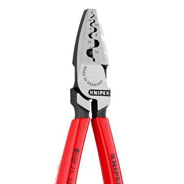
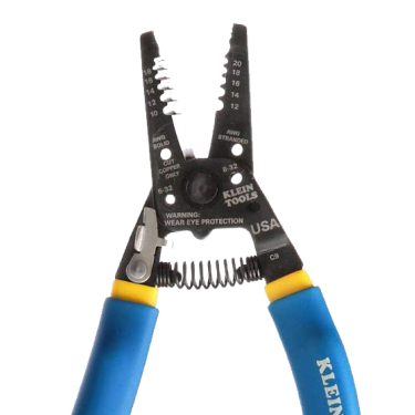
- Often multi-purpose pliers or wire strippers also show wire sizes. Make sure to buy a metric set when you are starting out.
 |
 |
 |
- Compare the wire against another wire whose gauge is known. For example, if you have a small-diameter section of wire, hold it next to wires of known gauge such as 0.5, 0.75 and 1.0 mm2 to see which wire your segment matches. Start collecting strands of various sizes of wire for future reference when you are working in the trade.

- Use a crimp lug to slip it over the cable to check the size.

Cable Markings
All the information you need to know about a type of cable is usually printed on its sheathing. This may include information about:
- Type of cable.
- Type of conductor.
- Presence of a grounding or earthing wire.
- Insulation used.
- Voltage rating.
- Temperature rating.
- Metre markings indicating how much cable has been used.
- Size and number of the individual conductors inside the cable e.g., 1mm2 – 32/0.2 cable has 32 strands of wire, each with a 0.2mm diameter.
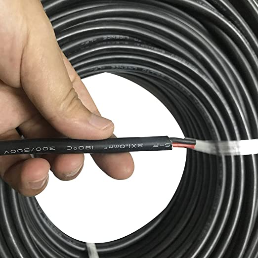
For instance, a cable marking of V-90 2.5 mm2 means the cable insulation is rated up to a maximum of 90°, has 2.5 mm2 conductors and has voltages rating as below.
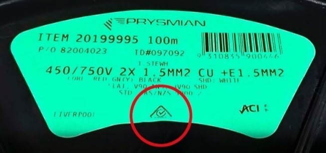
Manufacturers also include useful information on the cable drum labels.
Activity
This is included on the worksheet you downloaded for the previous activity under the heading Cable Label Activity.
Guided Activity
Work through the solution to the following problem, making sure you understand how each step was calculated.
A 240-volt single-phase air conditioner with a 20-amp load is located 30 m away from the power source. Use the AS/NZS 3008.1.1:2017 standard to calculate the minimum conductor size required for this application.
Solution:
1. Determine the load current: The load current is given as 20 amps.
2. Determine the voltage drop: (A maximum voltage drop of 5% for single-phase AC circuits is recommended in NZ.)
Using AS/NZS 3008.1.1:2017 the voltage drop can be calculated as follows:

Where:
Length = distance between power source and air conditioner, in metres
Load Current = 20 amps
Cross-sectional area = unknow, we will calculate this
Conductivity = 56.0 x 10² Siemens/metre (for copper conductors)
Plugging in the values, we get:

Rearranging this equation, we get:

3. Determine the resistance of the conductor: The resistance of the conductor can be found from the standard's tables. For a copper conductor, the resistance is 0.0085 ohms/metre.
4. Calculate the minimum cross-sectional area: Plugging in the values, we get:

A = 2.1 x 10⁻⁶ m2 or 2,100 mm2
Therefore, the minimum conductor size required for this application, according to the AS/NZS 3008.1.1:2017 standard, is 2,100 mm2.
In practice, this cable size may not be available, and the next largest standard cable size should be used instead.
Activity
Complete the question under the heading Cable Size Activity on the worksheet you downloaded previously.
Activity
Download this worksheet to complete the following exercises.
- Suggest at least one application for each of the following cables based on the conductor size and other information found on the label.
- TRS 1.5mm² 450/ 750V
- V-90 2.5mm² 450/ 750V
- NZXT 4mm² 450/750V
- What is the primary factor that determines the appropriate conductor size for an electrical installation in NZ?
- Why is it important to select the right cable size for an electrical installation?
- What are some consequences of using an undersized cable for an electrical installation?
- Complete the table which shows the information typically provided on the cable insulation and its importance in cable selection.
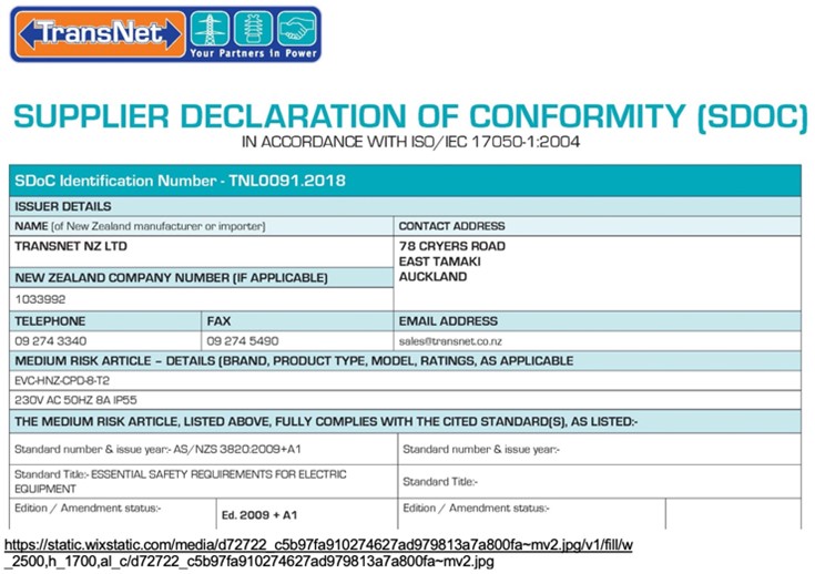
What we're covering:
- SDoC
- Installation and Connection of Appliances
- Testing and Compliance
Testing & Compliance
An electrical appliance is a device that is powered by electricity and performs a specific function or task. Common electrical appliances include refrigerators, washing machines, air conditioners, and televisions.

The Electricity Act 1992 defines electrical appliances as:
“Any appliance that uses, or is designed or intended to use, electricity, whether or not it also uses, or is designed or intended to use, any other form of energy.”
To ensure safe and effective installation you must consider several factors when installing an electrical appliance, including electrical load, voltage, location, grounding, wiring, circuit protection, installation instructions, declaration of conformity and manufacturer’s instructions.
Activity
Answer the first question on this worksheet, which you will use for the following 3 activities as well. Ask your tutor to check your answers when you are in class next.
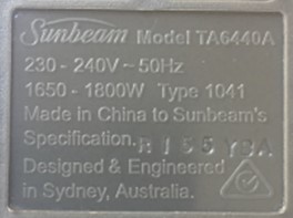
- Input specifications and ratings: The input specifications and ratings refer to the electrical requirements of the appliance, such as the voltage, frequency, and current rating and are typically listed on the appliance's label or in the user manual. You must consider these specifications when installing the appliance and ensure that the electrical system can provide the required input power.
- Control and power circuits: Electrical appliances typically have two types of circuits: control circuits and power circuits. Control circuits are used to control the operation of the appliance, such as turning it on and off, adjusting the temperature, or selecting a program. Power circuits are used to provide the energy needed to operate the appliance, such as heating elements or motors. You must ensure both circuits are working correctly for the appliance to operate safely and effectively.
- Electrical protection for appliances: Electrical protection is essential to prevent damage to the appliance and to ensure the safety of the users. Electrical protection devices include fuses, circuit breakers, and surge protectors. Use appropriate electrical protection devices to prevent electrical overloads, short circuits, and voltage surges.
- Appliance output: The appliance output refers to the results or output that the appliance produces, such as heat, light, or sound. Ensure the appliance output meets the user's needs and that it is safe and effective.
- Environment: The environment an electrical appliance operates can also affect its performance and safety e.g., appliances may need to be kept away from heat sources or in a well-ventilated area to prevent overheating.
- Energy efficiency: Choosing energy-efficient appliances can help to reduce your energy consumption and lower your electricity bills. Look for appliances that have a high energy rating or are certified by energy-saving organisations.
Examples:
| Appliance |
4 slice toaster |
| Input specifications and ratings | An 1800W toaster, requires a 10A socket and a 230V supply. The connection method needs to be rated correctly for the supply it is to be connected to. |
| Control and power circuits | Control circuits consist of a timer, a temperature control thermostat, and a switch that turns the heating elements on and off. Power circuits consist of two heating elements, made of nichrome wire, and a bimetallic strip that opens and closes the circuit to control the temperature. |
| Appliance protection |
The appliance is a Class I appliance and is earthed. Bimetal strip bends when heated, causing a switch to open and cut-off power to the toaster. (Strip returns to original position when cool, allowing normal operation to resume.) Thermal fuse breaks the circuit and cuts off power to the toaster in the event that the temperature inside the toaster exceeds a safe level. It cannot be reset. |
| Appliance output | Electrical energy is converted to heat energy by the nichrome wire heating elements causing the bread to become toasted. |

Activity
Answer the three questions under the heading Electricity Act in New Zealand on the worksheet you downloaded previously.
Installation and Connection of Appliances
In the NZ Wiring Rules (AS/NZS 3000:2018 Electrical Installations), there are 14 fundamental installation principles that represent a set of core requirements to be followed throughout the installation process, from design and selection of equipment to inspection and testing. While they are not listed in a single section, they are an essential part of the overall framework for electrical installations outlined in the Wiring Rules. These principles are as follows:
- Safety: The installation must be safe and not present a danger to people, animals or property.
- Functionality: The installation must function correctly and meet its intended purpose.
- Reliability: The installation must be reliable and not prone to failure.
- Accessibility: The installation must be accessible for maintenance, inspection and repair.
- Adequate capacity: The installation must have adequate capacity to handle the expected load.
- Protection against electric shock: The installation must provide adequate protection against electric shock.
- Protection against thermal effects: The installation must provide adequate protection against thermal effects, such as overheating.
- Protection against overcurrent: The installation must provide adequate protection against overcurrent.
- Selection of cables and conductors: Cables and conductors must be selected based on the electrical requirements of the appliance and the installation environment.
- Earthing and bonding: The installation must have adequate earthing and bonding to prevent electric shock and ensure proper functioning.
- Switching and isolation: The installation must have adequate switching and isolation to allow for safe maintenance and repair.
- Selection and installation of equipment: The equipment used in the installation must be suitable for its intended purpose and installed correctly.
- Inspection and testing: The installation must be inspected and tested to ensure compliance with regulations and safety requirements.
- Documentation: The installation must be properly documented, including records of design, installation, inspection, and testing.
Testing & Compliance of Fittings, Accessories, and Appliances
Once the electrical fittings, accessories and appliances have been installed, you must carry out inspection and testing as previously covered.
In New Zealand, after testing electrical appliances, a Certificate of Compliance (CoC) and an Electrical Safety Certificate (ESC) are typically required by regulatory authorities, insurance companies, and other stakeholders as proof of compliance and safety. Both demonstrate compliance with safety regulations and standards.
The CoC confirms that the installation or maintenance work has been carried out in accordance with the Wiring Rules and other relevant standards and regulations. It must be issued by a licensed electrician or an electrical inspector, and it includes details such as the date of the work, the location of the work, the type of work performed, and the electrical contractor's details.
The ESC confirms that the appliance has been tested and deemed electrically safe. It is usually issued by the electrician or testing technician who carried out the testing. The ESC includes details such as the date of testing, the location of the testing, the results of the tests, and any actions taken to rectify any faults or defects identified during testing.
Activity
Answer the questions on the worksheet that you downloaded for the previous activity.

What we're covering:
- Verification Test Sequence
- Extension cords and leads
- Testing Electrical Appliances
The AS/NZS 3000:2007 Verification Test Sequence is a series of tests and inspections that must be carried out to verify that the electrical installation is safe and compliant with the standard.

The Verification Test Sequence includes a range of tests and inspections, such as:
- Continuity of protective conductors: verifies that all the protective conductors are continuous
- throughout the electrical installation.
- Polarity of supply: checks that the live and neutral conductors are correctly connected.
- Insulation resistance: measures the resistance of the insulation between the conductors and earth.
- Earth electrode resistance measures the resistance between the earth electrode and the earth.
- Earth fault loop impedance: checks the impedance of the earthing system and determines the maximum fault current that can flow in the event of a fault.
- RCD testing: verifies the correct operation of residual current devices (RCDs), which are designed to protect against electric shock.
- Voltage drop: measures the voltage drop between the supply point and the end of the installation.
TESTING FLEXIBLE CORDS AND EXTENSION LEADS
In New Zealand, flexible cords and extension sets are inspected and tested to ensure they meet the safety requirements set out by the Electrical (Safety) Regulations 2010.
The testing process usually involves a visual inspection to check for any signs of damage, wear and tear or loose connections, followed by an electrical test to ensure the cable is properly insulated and has no exposed live parts.
The electrical test typically involves using a Portable Appliance Tester (PAT), which checks the cable's insulation resistance, polarity, earth continuity, and other electrical characteristics. If the cable passes the visual and electrical tests, it will be labelled with a tag indicating that it has been tested and is safe to use.
Visual Inspection
This includes the plug and socket as well as the cable. Refer to Clause 8.2.2 AS/NZS 3000:2007.
Activity
List the things you should visually check on your cord extension set on this worksheet, which you will use for the next activity as well.
Earth Continuity Test
An earth continuity test checks the integrity of the earth connection in an electrical appliance or piece of equipment, ensuring the earth wire is connected from the plug to the equipment or socket with sufficiently low resistance to provide a good fault current path ensuring circuit protection devices operate. The earth continuity conductor in all cord extension sets must have a resistance of <1.0 Ω between the plug earth pin and the earth socket/contact of the outlet(s).
https://carelabz.com/learn-continuity-testing-what-how/
- To carry out an earth continuity test on an extension set using a PAT, the following steps would typically be followed:
- Connect the extension set to the PAT using the appropriate test leads.
- Select the earth continuity test function on the PAT.
- Press the test button on the PAT to initiate the test.
- The PAT will typically apply a low voltage to the earth wire in the extension set and measure the resulting current flow.
- The PAT will display a pass or fail result based on whether the measured resistance falls within acceptable limits (as specified in the relevant electrical safety standards).
- If the extension set fails the test, it should be repaired or replaced before it is used again.
Specific details of how an earth continuity test is carried out may vary depending on the type of PAT being used and the procedures and requirements of the organisation or industry. Read more about the earth continuity test in NZECP 50:2004 Section 3.7 and AS/NZS 3760:2010, Appendix D.
Insulation Resistance Test
An insulation resistance test measures the resistance of the insulation material between two conductive parts of an electrical system. The test is used to detect insulation problems such as contamination, moisture, or damage, which can cause electrical leakage and create a safety hazard.
AS/NZS 3760, Appendix E explains the procedure for verifying the insulation resistance of flexible cords. Additionally, any testing of the appliance and cord must satisfy the requirements of AS/NZS 5762.
During the test, a high voltage DC signal (500V D.C. for low voltage installations) is applied between conductors i.e., A-N, A-E and N-E. and the resulting current flow is measured. Insulation resistance can be calculated using Ohm's Law. Insulation resistance between all conductors must be >1MΩ.
The test is typically performed using a specialised instrument called a megohmmeter or Insulation Resistance Testers. (Multimeters cannot produce the necessary 500 Volts to expose any weakness.)
The same technique may be used to test the phase and neutral conductors to ensure their connection and polarity is sound and verified.
Leakage Test
The leakage test also known as a dielectric test, is used to measure the amount of current that "leaks" from a device or component when it is operating under normal conditions. This test is typically performed by applying a lower voltage (e.g., 50V) to the device or component and measuring the resulting current. The goal of the leakage test is to ensure that the device or component is not leaking current in a way that could be hazardous to the user or damage the device itself.
Activity
Explain the difference between the leakage test and the insulation resistance test on the worksheet you downloaded for the previous activity
Polarity Check
A polarity check for extension cords involves verifying the correct wiring of the cord's plug and socket to ensure that the live and neutral wires are connected properly. The following steps are generally involved in performing a polarity check:
- Turn off the power to the extension cord and unplug it from the power source.
- Use a multimeter or a plug-in polarity tester to check the wiring of the plug and socket.
The tester should indicate that the live wire is connected to the correct pin on the plug and socket, and the neutral wire is connected to the correct pin on the plug and socket. If they are the wrong way around, the switch and fuse are in the neutral leg, which means that the appliance is live even when switched off and if a fault developed on the appliance, the fuse would not blow posing a risk of electric shock or fire.
Check - polarity of the plug top (earth, phase, neutral in a clockwise direction when viewed from the back of a single-phase plug-top) and socket.
Watch this brief video demonstrating how to test and tag extension leads using a portable appliance testing (PAT) machine.
How to test and tag.
Your tutor will also demonstrate the inspection and testing procedures and give you the opportunity to practice these.
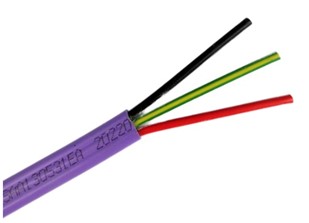
Multiphase Cord Test Procedure
The principle of inspection and testing multiphase cords is the same as for single phase cords.
- A visual inspection looking for any obvious defects; damage or deformation of the casing; inadequate cord grip on the plug cover; loose plug pins; etc.
- Electrical testing ensures the continuity resistance of the earth conductor is less than 1Ω; the insulation resistance between all conductors and conductors and earth is greater than 1MΩ and the polarity of the three-phase plug top (earth, L1, L2, L3 and neutral where it exists) is correct.
TESTING ELECTRICAL APPLIANCES
The specific requirements for inspection and testing of electrical appliances are outlined in the Electrical (Safety) Regulations 2010 and the New Zealand Standard for In-service safety inspection and testing of electrical equipment (AS/NZS 3760:2010).
The following steps are recommended for inspecting and testing electrical appliances in New Zealand:
- Visual inspection: A visual inspection should be performed to check for any signs of damage or wear and tear, such as frayed cords, broken plugs, or damaged casings.
- Electrical testing: Electrical testing should be performed using a Portable Appliance Tester (PAT) to ensure the appliance is functioning correctly and is electrically safe. This testing should include earth continuity, insulation resistance, and leakage current tests.
- Tagging and recording: Once the appliance has been inspected and tested, it should be labelled with a tag that includes the date of testing, the next testing due date, and the name of the person who performed the testing. The testing results should also be recorded in a register or database.
- Re-testing: The appliance should be re-tested at regular intervals, as specified in AS/NZS 3760:2010 or according to the manufacturer's instructions.
Specific testing requirements and frequency vary depending on the type of electrical appliance and its intended use.
Class I Appliances
Class I appliances are electrical appliances that are designed to be grounded or earthed. These appliances have exposed metal parts that require a ground connection for safety. The testing requirements include:
- Visual inspection: The appliance should be checked for any visible damage, such as cracks or frayed cords.
- Earth continuity test: The appliance should be tested to ensure that the earth connection is intact and has low resistance.
- Insulation resistance test: The appliance should be tested to ensure that the insulation between the live parts and the earth is adequate.
- Polarity test: The appliance should be tested to ensure that the active and neutral connections are correctly wired.
- Leakage current test: The appliance should be tested to ensure that the leakage current is within safe limits.
Class II Appliances
Class II appliances are those with double insulation or reinforced insulation to provide additional protection against electric shock. Even though they have fewer conductive parts than Class I appliances, they still require the same level of diligence when it comes to inspection and testing.
The specific requirements for inspection and testing of Class II appliances may vary depending on the type of appliance and its intended use, but typically include:
- Visual inspection: To check the condition of the appliance and its components, including the power cord, plug, and casing. It is often necessary to protect cable entry against wear and tear by using strain relief moulding as well as a cord grip clamp on the sheathing of the cord.
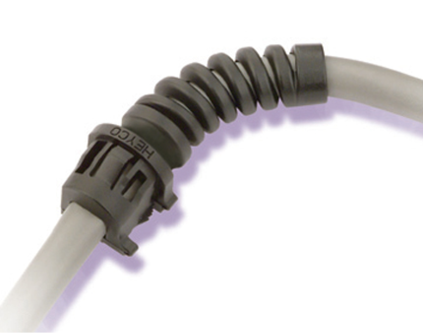
https://www.heyco.com/Strain_Relief_Bushings/img/4-12_114.jpg
- Electrical testing: Electrical testing should be carried out to ensure that the appliance is operating within safe limits. This may include testing for earth continuity, insulation resistance, and polarity. A leakage test should be done on appliances with internal switching that is only activated when the equipment is powered at operating voltage. For equipment that does not have internal switching, then a 500V insulation test is an acceptable alternative.
- Functional testing: Functional testing should be carried out to ensure that the appliance is operating as intended and that all safety features are working correctly. This may include testing the operation of switches, temperature controls, and other features.
- Tagging and recording: Once the inspection and testing have been completed, the appliance should be tagged and recorded to indicate that it has been tested and deemed safe for use. The tag should include the date of testing, the name of the person who carried out the testing, and any other relevant information.
According to AS/NZS 3000:2018 Electrical Installations, Section 5.4.1.3, electrical equipment must be earthed by one of the following methods:
- Connection to a protective earth (PE) conductor in the supply circuit.
- Connection to a local earth electrode, such as a grounding rod.
- Connection to a common earth point that is connected to the supply PE conductor or local earth electrode.
- Double insulation, which eliminates the need for an earth connection.
Earthing of the electrical equipment is not required for:
- Double-insulated equipment with two layers of insulation to provide protection against electric shock.
- Safety Extra Low Voltage (SELV) and Protective Extra Low Voltage (PELV) equipment designed to operate at very low voltages (typically less than 50 V AC or 120 V DC), which eliminates the risk of electric shock.
- Portable equipment that is not connected to a fixed electrical installation however, it must be designed and maintained to ensure that there is no risk of electric shock.
- Class III equipment designed to operate at extra-low voltages (less than 25 V AC or 60 V DC) and also known as a Safety Extra Low Voltage (SELV) circuit.
Residual Current Devices
Residual Current Devices (RCDs) are required to undergo regular inspections and testing to ensure their continued effectiveness. The specific requirements for inspection and testing of RCDs may vary depending on the jurisdiction and the type of RCD, but some general guidelines are:
- Visual inspection – replace your RCD if there are any signs of damage.
- Operating current ≤ 30mA.
- Earth continuity test.
- Insulation /Leakage test.
- Trip Time Test – performed at intervals specified in Table 4 AS/NZS 3760:2010. Either press the test button (and check that the power switches off) or use an RCD Tester to check the trip current and trip time. In New Zealand & Australia AS/NZS3760 requires only an AC test to be done.
https://www.bmselectrical.com.au/images/services-compliance.jpg
Activity
Read through the scenario below and answer the following question, putting yourself in the shoes of a working site manager tasked with ensuring the electrical safety of everyone on site.
- What are the key steps the site manager must take to ensure compliance with the regulations for inspecting and testing electrical equipment? Post your ideas on the class forum page.
Note - The New Zealand Electrical Code of Practice for Electrical Safe Work (NZECP 50:2010) provides guidelines for electrical safety in the workplace, including inspection and testing of electrical equipment.

What we're covering:
- types of support systems
- selection and installation requirements
- moisture and fire barrier ratings
There are several common electrical cable support systems used in New Zealand and Australia. These include:
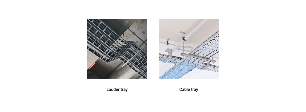
Cable trays: These are metal (galvanised steel, stainless steel or aluminium), or plastic trays used to support and protect cables. Cable trays come in a variety of sizes and can be used in many different types of installations – especially if changes to a wiring system are likely. It is much easier to install new cables in a tray than to pull them through conduit.

Solid-bottom cable trays offer more protection to cables than ventilated trays but in order for cables to enter or exit the tray they must either be cut, or fittings must be used.
What are some situations where you might choose ventilated cable trays rather than solid bottom?
- areas where dust is an issue
- to allow free flow of air to reduce heat and moisture
- to allow multiple exit points for the cables through the top or bottom of the tray
- easy installation and access for small cables
Conduit: Electrical conduits are metal, plastic, or fibre pipes designed to protect and route electrical wiring. It is often made of metal or plastic and comes in different sizes depending on the application. Rigid conduit is most commonly used however flexible conduit is ideal for the last few metres of wiring, where conventional conduit systems are difficult to maneuver and terminate.
AS/NZS 3000 requires insulated, unsheathed cables to be enclosed in a wiring enclosure such as conduit or ducts throughout their entire length.
Long runs of conduit require additional support to keep them from sagging or breaking under their own weight. Straps are used to mount the conduit to ceilings or walls using a screws or bolts. To fasten conduit runs to fixed structures, the conduit is supported using clamps.

What is the difference between conduit and duct?
Used for above ground cables and inside buildings
Used for protection of underground cables
Cable ladders: Also referred to as a ladder tray or cable runway; cable ladders are like cable trays but have a more robust design. They are typically made of metal and are used to support heavier cables and wiring.
Cable trays with covers: Like cable trays, these systems have a cover that provides additional protection to the cables against UV, dust, snow/ice and vandalism.

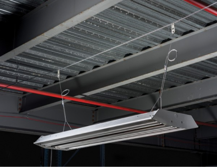
Catenary wire: ‘Catenary’ describes the shape of the curve formed by a freely hanging wire between two points. A catenary system has come to mean a method of support for cable in which cable is spread from one point to another by means of hanging it between two points through a catenary wire. The electric cable is attached to the catenary wire with cable ties or straps. A catenary wire rope is usually made from galvanised steel wire which can be PVC-coated, or it can be made from stainless steel wire. A high strength-to-weight ratio ensures it can support the load and any mechanical stresses. It should be mounted at sufficient height to prevent danger to those below.
blog.nvent.com/catenary-ideal-for-hanging-in-large-structures/
Refer to AS/NZS 3000:2007 Clause 3.13 for details of cables that can be supported by catenary; requirements of a catenary support; and details of clearances.
- Cable trunking: This is a plastic or metal channel used to hide and protect cables. It is often used in offices and homes to conceal electrical wiring.
- Cable clips: These are plastic or metal clips used to secure cables to walls or other surfaces. They are typically used in smaller installations.
- Cable cleats: Cable cleats are used to secure cables to walls or other surfaces in high-vibration environments, such as in industrial or mining applications.
The specific types of electrical cable support systems used will vary depending on the location, application, and industry.
Activity
Download the worksheet and answer the questions on cable support systems.
CABLE SUPPORT SYSTEM SELECTION REQUIREMENTS:
- Load capacity: The cable support system should be able to support the weight of the cables and any additional equipment that may be attached to it.
- Material: The material used for the cable support system should be appropriate for the environment in which it will be installed. For example, if the system will be installed in a corrosive environment, a material that is resistant to corrosion should be used.
- Size: The size of the cable support system should be appropriate for the cables it will be supporting. The system should be large enough to allow for any necessary future expansion.
- Fire rating: The cable support system should have a suitable fire rating to prevent the spread of fire in the event of an electrical fault.
CABLE SUPPORT SYSTEM INSTALLATION REQUIREMENTS:
- Location: The cable support system should be installed in a location that is easily accessible for maintenance and inspection.
- Height: The height at which the cable support system is installed should be appropriate for the type of cables it will be supporting. The system should be installed at a height that allows for safe and easy access.
- Support spacing: The spacing between supports should be appropriate for the weight of the cables and any additional equipment that may be attached to the system.
- Fixing: The cable support system should be securely fixed to the structure it is attached to using appropriate fixings.
- Cable protection: The cable support system should provide adequate protection for the cables it supports, preventing damage from external factors such as water, heat, or mechanical stress.
- Earthing: The cable support system should be earthed to prevent the build-up of static electricity, which can be a safety hazard
- Labelling: The cable support system should be clearly labelled to indicate the type of cables it supports and any relevant information about the system.
As previously mentioned, extra low voltage cables must not be installed near low voltage cabling.
Where cables are installed in parallel, steps should be taken to reduce the effects of mutual inductance.
| To reduce unwanted inductance between 3-phase conductors in parallel |  |
|---|---|
|
 |
|
 |
It is important to consult relevant codes and standards, to ensure compliance with all applicable regulations and best practices when selecting and installing electrical cable support systems in New Zealand.
MOISTURE AND FIRE BARRIER RATINGS
Moisture and fire barrier ratings for electric cable penetrations are important to ensure safety and protection of buildings from potential damage caused by fire or water. The general principles for these ratings in New Zealand and Australia are as follows:
Moisture Barrier Ratings: Moisture barrier ratings are used to prevent water or moisture from penetrating electrical cable penetrations. As mentioned previously, the IP (Ingress Protection) rating system is used in NZ. A typical moisture barrier rating for electrical cable penetrations would be IP67, which means that the penetration is completely protected from dust and water.
Fire Barrier Ratings: Fire barrier ratings are used to prevent the spread of fire through electrical cable penetrations. The Fire Resistance Level (FRL) rating system indicates the level of fire resistance of a particular material or structure. The FRL rating system is a combination of three components:
- Structural adequacy (load-bearing capacity).
- Integrity (ability to prevent fire spread).
- Insulation (ability to prevent the transmission of heat).
A typical fire barrier rating for electrical cable penetrations would be FRL60/60/60, which means that the penetration can withstand a fire for 60 minutes without losing its structural integrity, integrity of the seal, or insulation. An FRL of 120/60/60 means the building element has a load-bearing capacity for 120 minutes and can prevent the spread of fire and prevent the transmission of heat for 60 minutes.
In general, the FRL rating of an electrical installation will depend on the type of installation and its location within the building. For example, electrical wiring and equipment installed in a fire-rated compartment, or a fire-resistant wall will need to have a higher FRL rating than those that located in an open space.
Compliance: All electrical cable penetrations comply with the relevant national standards and codes. For example, in New Zealand, the Building Code requires that all electrical cable penetrations meet the standards set out in NZS 4219:2009, which outlines the requirements for fire safety in buildings. The Code specifies minimum FRL ratings for different building elements, including electrical installations. For example, the Building Code requires electrical cables and wires to have a minimum FRL rating of 30/30/30 when they are installed in fire-rated walls or floors. This means that the electrical cables and wires should be able to resist fire for at least 30 minutes in terms of structural adequacy, insulation, and integrity.
AS/NZS 3000 1.5.12 outlines the protection to be provided against fire initiated or propagated by components electrical installation. AS/NZS 3000 3.9.9 and Appendix E also cover the selection of appropriate materials and installation methods to minimise the spread of fire.
Installation: It is important to ensure that all electrical cable penetrations are installed correctly and according to the manufacturer's instructions. This may involve the use of appropriate fire-resistant materials, such as firestop sealants, collars, or pillows, to ensure that the penetration is adequately sealed and can withstand the required fire rating.
Electrical systems can be a significant source of ignition for fires. Faulty wiring, overloaded circuits, and other electrical hazards can all increase the risk of a fire breaking out.
Active fire protection and passive fire protection are two different approaches to managing the risk of fire in buildings. While both are important in ensuring the safety of occupants and limiting property damage, they differ in terms of their function and operation.
Active fire protection systems are designed to detect and suppress fires quickly, often before they have a chance to grow into a larger blaze. Examples of active fire protection systems include fire alarms, smoke detectors, fire sprinklers, and fire extinguishers. These systems require regular maintenance and testing to ensure they are functioning properly. They are usually activated automatically in response to a fire or manually by building occupants.
Passive fire protection, on the other hand, is designed to contain the spread of fire and smoke within a building, limiting damage and allowing occupants to evacuate safely. Passive fire protection measures include fire-resistant building materials such as fire-rated walls, doors, and windows, as well as firestops, fire dampers, and fire-resistant coatings. These measures do not require any active intervention and are intended to work even in the absence of power or human intervention.
When electrical or communication cables are installed through a fire wall or floor, steps must be taken to maintain the fire rating of the structure.
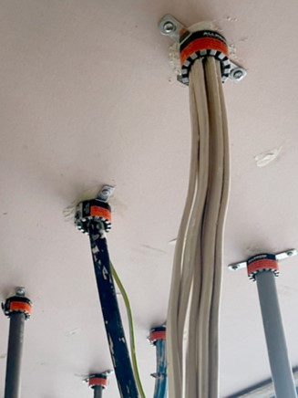
AS/NZS 3000 3.9.9.3 describes the requirements for cables passing through elements of building construction that are required to be fire-rated.
When installing wiring, it is important to identify any wall, floor or roofing material that may form part of a fire cell structure.
Activity
The questions for this can be found under the heading Fire-rated penetration seals on the worksheet you downloaded for the previous activity. Email your answers to your tutor.
What we're covering:
- purpose of mains
- mains cable selection
Consumer mains and sub-mains are both electrical cables that are part of a building's electrical distribution system, but they serve different purposes.
Consumer mains or simply mains, are the primary electrical cables that connect a building's main distribution panel to the local utility grid, typically at a high voltage level. These mains are responsible for delivering power to the entire building and are designed to handle high current loads.
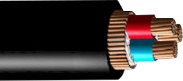
Note
Consumer mains and consumer cables are not the same thing. Consumer mains are the primary electrical cables that deliver power to a building, while consumer cables are the secondary cables that distribute power to individual circuits or loads within the building.
Submains, on the other hand, are electrical cables that branch off the main distribution panel and provide power to specific areas or zones within the building. They carry lower voltages than the mains and are used to distribute power to specific circuits or loads in a more efficient and organised manner. Submains can be used to connect multiple panels or switchboards within a building and can also be used to distribute power to remote locations or outbuildings. They are protected from both over-load and short circuit current at the main distribution board.
Common cables used for mains cables include:
- PVC-insulated cables - These are commonly used for low voltage applications, where the current is relatively low. Flat PVC sheathed cable with two to four copper conductors is the most commonly used cable in New Zealand for fixed wiring in buildings.
- XLPE-insulated cables - These cables are used for high voltage applications, such as in power transmission lines or industrial settings.

- Rubber-insulated cables - These are commonly used for outdoor or harsh environmental conditions, as they offer excellent resistance to temperature changes, moisture, and abrasion.
- Armoured cables - These cables have an additional layer of protective armour, usually made of galvanized steel or aluminum, to provide additional protection against physical damage and moisture. Armoured cables are used for underground and outdoor installations where protection against mechanical damage is required.
- Non-metallic sheathed cables - These are commonly used in residential wiring applications, such as for wiring outlets and light fixtures.
Mains Cable Selection Process
Maximum Demand
Maximum demand during cable installation is determined by calculating the maximum amount of electrical power that is likely to be required (under normal operating conditions) by the electrical system or equipment that the cable is intended to serve. This helps to ensure that the cable is able to carry the required electrical load safely and efficiently without being overloaded.
To determine the maximum demand, the following factors are typically considered:
- Electrical Load: The maximum demand is calculated based on the total electrical load that the cable will be required to carry. This includes the power consumption of all the electrical equipment and appliances that will be connected to the cable.
- Cable Length: The length of the cable and the resistance of the conductor material used also affect the maximum demand calculation. Longer cables have higher resistance, which results in higher voltage drop and less current delivered at the end.
- Ambient Temperature: The ambient temperature of the location where the cable will be installed also plays a role. Higher temperatures can cause the cable to heat up and increase its resistance, reducing the amount of current that can be safely carried.
- Voltage: The voltage level of the electrical system also affects the maximum demand calculation. Higher voltage systems can carry more power than lower voltage systems, so the maximum demand for a cable in a high voltage system will be higher than for the same cable in a low voltage system.
- Future Expansion: The maximum demand calculation should also consider the possibility of future expansion or growth of the electrical system, which could increase the load on the cable
Your selection criteria for mains cable should also include these factors:

- Voltage rating: The cable must be rated for the voltage of the electrical system in which it will be used. In New Zealand, the standard voltage is 230-240 volts AC
- Current carrying capacity: The cable must be able to safely carry the maximum current that will flow through it. The current carrying capacity is determined by the cable's cross-sectional area (gauge) and is specified by the manufacturer.
- Number of cores: The cable must have the appropriate number of cores for the application. For example, a three-core cable is typically used for most electrical applications in New Zealand, with one core for the live conductor, one for the neutral conductor, and one for the earth conductor.
- Insulation and sheathing: The cable must be insulated to prevent electrical shock and must have a protective sheath to prevent damage to the cable. The insulation and sheathing materials used must comply with local standards and regulations.
- Temperature rating: The cable must be able to withstand the temperatures it will be exposed to during use. In New Zealand, cables are typically rated for temperatures up to 75°C or 90°C.
- Environmental rating: The cable must be rated for the environment in which it will be used, such as indoor or outdoor use, exposure to moisture or chemicals, and exposure to UV light.
- Compliance with standards: The cable must comply with local standards and regulations. AS/NZS 3008:2017 Electrical installations - Selection of cables should be used in conjunction with other standards and regulations, such as AS/NZS 3000 (the Wiring Rules), Electricity (Safety) Regulations 2010 and AS/NZS 5000.1 (the Cable Standard).
- Length of cable: The length of the cable should be considered to ensure it reaches the electrical socket without being too long and creating a trip hazard.
Read through the following examples of selecting a cable. Make sure you understand what is happening at each step. Check any calculations as you read to ensure that you get the same answers as the examples.
Example 1
Select an underground mains cable for a single-phase (230V) domestic dwelling in New Zealand that has a maximum demand of 65A. Cable length is 20 metres and the cable must have no more than 3.5% volt drop from the point of supply.
Using an online voltage drop calculator with the given parameters, we can determine that the maximum allowable voltage drop is 8.05 volts (3.5% of 230V).
To find a suitable cable, we can refer to the New Zealand Electrical Code of Practice for Electrical Wiring Work in Domestic Premises (AS/NZS 3008.1.1:2017)*, which provides tables for selecting cables based on voltage drop and current capacity.
Based on the maximum allowable voltage drop of 8.05 volts, we can use Table 4.5.1 of the code to find suitable cables sizes for a 20 metre run.
For a maximum demand of 65A, the minimum cable size required to meet the voltage drop limit is 25 mm2 copper. This cable isze has a voltage drop of approximately 5.1 volts per 100 metres, which is well below the allowable limit for the given parameters.
Therefore, a suitable underground mains cable ofr a single-phase (230V) domestic dwelling in New Zealand with a maximum demand of 65A and a cable length of 20 metres is a 25 mm2 copper cable.
A suitable 25 mm2 copper cable for direct burial would be a 2-core or 3-core XLPE (Cross-Linked Polyethylene) insulated cable.
*Table 1.5 of the code provides cable sizes for given maximum voltage drop and maximum current ratings for various installation methods, such as conduit, trunking, or direct burial.
*Table 4A of the code provides information on cable types and sizes for various installation methods, including open cable trays, closed cable trays, and direct burial.
Example 2
Select a three phase (400V) industrial building submain cable with a maximum current requirement of 105A per phase. The cable will be run in an open cable tray. The selected cable needs to have a volt drop of less than 1.75 mV/A/m.
Using an online voltage drop calculator with the given parameters, we can determine that the maximum allowable voltage drop is 183.75 volts (1.75 mV/A/m x 105A x 100m).
To find a suitable cable, refer to the NZCP for Electrical Wiring Work (AS/NZS 3008.1.1:2017), which provides tables for selecting cables based on voltage drop and current capacity.
Based on the maximum allowable voltage drop of 183.75 volts, we can use Table 1.5 of the code to find suitable cable sizes ofr a 100 metre run.
For a maximum current requirement of 105A per phase, the minimum cable size required to met the voltage drop limit is 120mm2 copper. This cable size has a voltage drop of approximately 1.5 mV/A/m, which is allowable limit for the given parameters.
For an open cable tray installation, we can refer to Table 4A of the code to find suitable cable types. Based on the current rating of 105A per phase, a suitable type would be a 4-core XLPE (Cross-Linked Polyethylene) insulated cable with a steel wire armour for mechanical protection.
Therefore, a suitable three-phase (400V) industrial building submain cable with a maximum current requirement of 105A per phase, and a maximum volt drop of 1.75 mV/A/m for an open cable tray installation is a 120mm2 4-core XLPE insulated copper cable with steel wire armour.

What we're covering:
- common types of fittings
- selecting the right fitting
Electrical fittings are a very important aspect of electrical work and electrical safety.
The Electricity Act 1992 defines electrical fittings as meaning:
“Everything used, or designed or intended for use, in or in connection with the generation, conversion, transformation, conveyance, or use of electricity.”
Note
“Accessories” is an alternative name for fittings. You will encounter both terms in the electrical industry.
There are many types of electrical fittings, but some of the most common ones include:
- Power points or socket outlets.
- Switches.
- Light fittings to hold and connect light bulbs.
- Ceiling roses.

- Circuit breakers and fuses to protect electrical circuits.
- Electrical conduit to protect and route electrical wiring.
- Cable trays: These are used to support and organize cables.
- Junction boxes to house electrical connections.
- Electrical connectors to connect wires and cables together.

- Cable clips and ties to secure cables to walls and surfaces.
- Permanent connection units.
- Distribution boards to distribute electricity throughout a building.

- Flexible cords connected to any permanent connection unit, ceiling rose, or cord grip lamp-holder.
Activity
Test your understanding of electrical fittings on these multichoice questions.
Selecting the Right Fitting
The selection criteria for an electric fitting depends on the specific application, but some common factors to consider when selecting an electric fitting are:
- Electrical specifications: The electrical specifications of the fitting, such as voltage, current, and frequency, must match the requirements of the installation. Current limits and voltage limits determine the maximum amount of current or voltage that the fitting can safely handle.
AS/NZS 3000 4.1.2. specifies the minimum requirements for the selection and installation of electrical equipment, including appliances and accessories, to satisfy Part 1 of the Standard.
Take into consideration any external influences such as thermal insulation in ceiling spaces and walls when you are making your selection of fittings (see NZECP 55).
- IP rating: You will recall the Ingress Protection rating is used to indicate the level of protection that an electrical fitting provides against the intrusion of foreign bodies (dust, dirt etc) and moisture. For example, a high IP rating is required for electrical fittings installed in outdoor areas or near water sources to prevent damage and ensure safe operation.

AS/NZS 3000 6.2. covers the general requirements for electrical installations in damp locations, providing guidance on the types of fittings suitable for damp locations and the minimum distances that must be maintained between electrical fittings and water sources to prevent electrical shock.

AS/NZS 3000 6.3. covers specific requirements for electrical installations in particular damp locations, such as bathrooms, showers, and swimming pools, with more detailed guidance on the types of fittings suitable for each location. It also specifies the requirements for electrical bonding and earthing in these locations.
The Electrical (Safety) Regulations 2010, Part 4 deals with the installation of electrical fittings in damp locations. A damp location is defined as an area that is subject to moisture, such as a bathroom, shower room, laundry room, or swimming pool area. The Regulations also specify the minimum clearance distances between electrical fittings and water sources, such as taps, sinks, and showers.
- Type of switch: An ordinary switch turns the power on or off to a particular electrical device or system. It is typically used to control lighting, fans, or other types of appliances. When an ordinary switch is turned off, it simply breaks the connection between the power supply and the device or system.
An isolator switch is used to completely isolate a circuit or electrical system from the power supply. It is designed to provide a physical break in the circuit, which can be useful for maintenance or repair purposes. When an isolator switch is turned off, it not only breaks the connection between the power supply and the device or system, but it also physically separates the circuit from the power supply.

Isolator switches are typically designed to handle higher currents and voltages than ordinary switches because they are often used to isolate high-power equipment, such as motors or industrial machinery.
Choosing switches suitable for circuit isolation is important because improper isolation can result in electrical shock or damage to equipment. Switches should be rated for the voltage and current of the circuit and should have appropriate mechanical and electrical interlocks to prevent accidental switching.
- Position of switches: The position of switches in a circuit also determines the type of switch fitting installed because different types of switches are designed for specific applications and installation requirements. They should be positioned to allow for easy access in case of emergency or maintenance, and they should be clearly labelled to indicate their function. In addition, switches should be positioned in a way that prevents accidental or unauthorised operation, especially for critical systems such as emergency lighting or fire alarm systems.
An intermediate switch, for example, is a type of switch used to control a single lighting circuit from three or more different locations. In a multi-way switching system, the intermediate switch is placed between two two-way switches and is used to control the same lighting circuit. When the intermediate switch is in the "on" position, it allows current to flow through the circuit and turn the light on. When it is in the "off" position, it breaks the circuit and turns the light off. In a long hallway with several entry points, intermediate switches can be installed at different points along the hallway, allowing the lights to be turned on or off from any of these locations.
Also take into account these factors in your selection of fixtures:
- Compatibility: The fitting must be compatible with other components of the electrical system, such as cables, circuit breakers, and switches.
- Safety: The fitting must meet relevant safety standards and regulations to ensure safe operation.
- Durability: The fitting must be able to withstand the environmental conditions and mechanical stresses of the installation location.
- Cost: The fitting must be affordable and provide good value for money, taking into account its lifespan, maintenance requirements, and energy efficiency.
- Ease of installation: The fitting should be easy to install and connect to other components of the electrical system.
- Aesthetics: The fitting should be aesthetically pleasing and fit in with the overall design and style of the building or installation.
- Wiring: The wiring should be of the correct size, type, and insulation for the electrical fitting or accessory.
- Access: You need to consider how easy it will be to access the electrical fitting or accessory for maintenance or repairs.
- Code Compliance: You need to ensure that the installation complies with all applicable electrical codes and regulations.
- Grounding: You need to ensure that the electrical fitting or accessory is properly grounded to prevent electrical shock.
Activity
Are the following statements true or false? Then match the following electrical fittings with their appropriate use.
Activity
Locate the answers to the questions in this worksheet by referring to the appropriate standard and share them on the class forum.
What we're covering:
- Section 3.9 AS/NZS 3000:2018
- Suitability of Materials
Section 3.9 of AS/NZS 3000:2018 provides detailed guidance on the mounting and support requirements for electrical fittings and components, with a focus on ensuring that they are installed in a safe, robust, and secure manner, and that they are protected from mechanical damage and excessive heat.
Specifically, section 3.9 of this standard outlines the following mounting and support requirements:
- All fittings and components must be securely mounted and supported so as to prevent displacement or mechanical damage during installation, operation or maintenance.
- The mounting and support arrangements must be robust and suitable for the intended purpose of the fitting or component.
- The mounting and support arrangements must not place undue stress on any part of the fitting or component.
- Fittings and components must be supported in a manner that will allow adequate ventilation to prevent excessive heat build-up.
- Where necessary, protective devices such as shrouds must be used to protect fittings and components from mechanical damage.
- Fittings and components must be securely fastened to their supporting structure, and this may involve the use of suitable brackets, clips, or other fastening devices.
- Where a fitting or component is to be mounted on a surface that is not rigid, additional support may be required to prevent it from becoming loose or damaged.
Suitability of Building Materials for Mounting Electrical Fittings
It is important to know about the strength and fire resistance of a building material when installing electrical fittings because electrical systems can generate heat and create potential fire hazards. If the building material is not strong enough to support the weight of the electrical fittings, there is a risk of them falling off and causing damage to the electrical system or injuring someone nearby. Similarly, if the building material is not fire-resistant, it can catch fire and spread quickly, posing a significant risk to the building's occupants.

Common building materials used in New Zealand can vary in their strength of mounting and fire resistance. Here are some comparisons:
- Timber: Popular for building due to its availability, strength, versatility, and relatively low cost. It is often used for framing, flooring, cladding, and decking. When properly treated and installed, it can be strong enough to support heavy loads. and it can also be strengthened by laminating or cross laminating the wood. Timber is highly combustible and can contribute to the spread of fire however treatment with fire-resistant chemicals improves its fire resistance.
- Concrete: Concrete is a strong, durable, and fire-resistant material commonly used for foundations, walls, and flooring. It can withstand heavy loads and has good fire resistance however concrete is heavy and requires specialised equipment for installation. It is relatively low-cost, easy to work with, and has good thermal properties.
- Masonry: Masonry, which includes brick, stone, and concrete blocks is another strong and durable building material with good fire resistance. It is also relatively low-maintenance and can provide good insulation, however, it can be expensive, heavy and it may require specialised skills to install.
- Steel: Steel is a strong and durable building material that can support heavy loads and has good fire resistance. It is also relatively lightweight and commonly used in structural elements such as beams, columns, and frames. It is lightweight and easy to install, however steel can be expensive compared to other materials.
- Plaster board: Plaster board, also known as GIB, gypsum board, or drywall, is a lightweight and cost-effective material used for interior walls and ceilings. It is easy easy to work with and can be cut to size, but it is not as strong as other building materials and may not be suitable for heavy loads. Plasterboard has poor fire resistance and may require additional fire protection measures.
- Polystyrene is a synthetic polymer material commonly used for insulation, cladding, and other construction applications. While it can be used for insulation or as a lightweight cladding material, it has relatively low strength and is not typically used for structural elements in buildings. Polystyrene is a thermoplastic material, which means it can melt and ignite under high temperatures. Polystyrene foam insulation is typically treated with fire-retardant chemicals to improve its fire resistance. However, even with these treatments, it may still burn and emit toxic gases when exposed to fire.
- In summary the following table compares common building materials used in New Zealand, based on their strength of mounting and fire resistance:
Consruction Material Strength of Mounting* Fire Resistance** Timber Good Poor to Fair Concrete Excellent Excellent Masonry Excellent Excellent Steel Excellent Good GIB Plasterboard Poor Fair Polystyrene Poor Poor Glass Poor to Fair Poor to Fair
* Strength of Mounting refers to how well a material can hold weight and resist forces, such as wind and earthquakes.
** Fire Resistance refers to how well a material can resist fire and prevent it from spreading.
Activity
Study the table comparing strength and fire resistance properties of different building materials then answer the questions in the worksheet.
| Material | Strength Rating | Fire Resistance Rating | Combined Rating |
|---|---|---|---|
| Concrete | 8 | 9 | |
| Timber | 7 | 7 | |
| Brick | 6 | 8 | |
| Plasterboard | 3 | 5 | |
| Steel | 9 | 8 |

What we're covering:
- Flexible cord
- Plugs and sockets
Flexible Cords
Flexible cords are used to connect electrical equipment to a power source. They are designed to be routinely flexed. Flexible cords may have an electrical plug that connects to a power source, or they may be permanently wired into a power source. Extension cords (cord sets), cables, and appliance cords are types of flexible cords.
Extension Cords
An extension cord is a length of flex with a plug on one end and a socket on the other end (usually of the same type as the plug). They tend to be used in situations where they are prone to damage – the insulation may be pinched, crushed, or scraped; the plug and socket connections may be pulled on excessively; overloading may cause the insulation to melt etc. Extension cords must be tested and tagged at specific time intervals when they are used commercially.

Note - extension cords can only carry full rated current when completely extended. If the cord is coiled up the heat produced from the resistance cannot dissipate and is instead trapped between the tightly coiled cable, resulting in fire or shock.
Appliance cords
An appliance cord is used to connect appliances to a power supply. It is made from insulated, flexible electrical cable with connectors at one or both ends.

One end is typically a male connector (recognised by its unshielded electrical prongs when it is disconnected) that goes into the wall outlet or extension cord. The other end is a female connector that is attached to the appliance or to another male connector. The female connector has one or more recessed holes with electrical terminals inside and is constructed in such a way that a plug with exposed conductors (a male connector) can be inserted snugly into it. This female connector is sometimes omitted in appliances and replaced by a fixed cable.

Plugs and Sockets
There are currently 15 different styles of outlets and plugs commonly used around the world.

New Zealand, Australia and the Pacific Islands use Type I plugs. Type I plugs have three flat pins in a triangular pattern - two angled at the top and one straight underneath.

Socket Configurations
Plug tops and sockets are available in a range of pin styles and configurations. This convention prevents an appliance being supplied from socket outlets of a higher current rating. (A plug can be inserted into a socket of the same or higher rate, but not in a socket with a lower rate.)
Standard single phase 230 V domestic socket outlets in Australia and New Zealand are rated at 10 A. Some single-phase plug and socket configurations are shown:
| Rating | Socket Image | Description |
|---|---|---|
| 10A 250V |  |
Standard domestic configuration _ three flat pins - phase, neutral, and the largest - the earth pin. |
| 15A 250V |  |
Wider Earth pin than the 10 A outlet. |
| 10A 250V |  |
Configuration for special purposes - flat phase and neutral pins and round earth pin _ such as "off peak" storage heaters etc. |
| 20A 250V |  |
Wider earth and wider phase and neutral pins than the 10 A outlet. |
| 10A 250V |  |
Suitable for utility, industrial and small commercial installations. |
| 20A 250V | |
Suitable for most industrial and commercial applications. |
| 32A 250V |  |
Industrial strength power plugs for dusty or wet conditions. |
Voltage and Current Rating
As we have seen, a plug top must have a voltage and current rating not less than that of the appliance it supplies and its intended socket. Sockets accept equal and lower rated plugs, so a 32A outlet accepts 32A, 25A, 20A, 15A, 10A and 7.5A plugs, but a 10A outlet will only accept 10A and 7.5A plugs.
Ingress Protection (IP) Rating
An IP mark, (also referred to as an International Protection mark) is a two-digit grading system applied to electrical equipment. The IP rating denotes:
- Resistance to ingress, accidental or otherwise, by the user.
- Resistance to ingress from foreign bodies (dust, dirt etc.).
- Resistance to moisture ingress.
The first digit will be a number between 0-6 and indicates the degree of protection from ingress of solid objects, while the second digit will be a number between 0-9, denoting the quality of resistance to moisture ingress at varying intensities, angles, depths and pressures of exposure or immersion.
An IP66 rating means the fixture is protected against dust, dirt, sand, and debris (indicated by first “6” digit)and is water resistant against powerful jets (indicated by second “6” digit)

An explanation of IP ratings is available in AS/NZS 3000 Appendix G.
Activity
Why is it useful to have a universal rating system? Email your answer to your tutor.

What we're covering:
- Multiphase cords and plugs
- Flexible cord entry supports
Multiphase Cords and Plugs
In a three-phase supply system, there are two different levels of voltage - the lower voltage is the 'Line to Neutral Voltage' which is the measured voltage between one of the three lines and the neutral, and the higher voltage is the 'Line to Line Voltage'.
For instance, in a 400/230V three-phase and neutral system, voltage between any two phases/lines is 400V and voltage between any phase/line and neutral is 230V.

This setup allows you to connect a three-phase load in a way that each phase will have either 230V or 400V across them or connect a single-phase load that needs 230V across one phase and neutral.
Multiphase Plugs and Socket Outlet Configurations
Multiphase plugs and socket outlets are available in a wide range of styles. They are rated up to 500 V and all include an earth connection.
Three-phase plugs and sockets are available as 4-pin (without neutral) or 5-pin (with neutral). A plug without a neutral pin can be inserted into a socket carrying neutral, but the reverse is not possible since there is hole for the neutral conductor.

AS/NZS 3123 groups three-phase, round-pin sockets according to their current rating and neutral circuit:
| Group | Maximum Current Rating | Neutral Circuit | Neutral Conductor Colour |
|---|---|---|---|
| 1 | 10 amps | N | N/A |
| 2 | 20 amps | Y | Light Blue |
| 3 | 32 amps | Y | Light Blue |
| 4 | 50 amps | Y | Light Blue |
| 5 | 50 amps | Y | Black |
| 6 | 50 amps | Y | White |
The selection of the appropriate group depends on the specific application and the maximum current rating required. It is also important to connect the load to the appropriate phase conductors and neutral conductor according to the colour coding specified for that group.
Activity
Download this worksheet and answer the questions. Bring it to class for your tutor to check.
Each socket in the group accepts plugs in the same group up to its rating but excludes plugs with a higher current rating; from a different group; or with a neutral pin (if there is not one in the socket).
| Plugs | Sockets | ||||||||||||||||
| Group | Voltage | Current | 110V 1ph | 250V 1ph | 415-500V 3ph | ||||||||||||
| Group 5/6 | Group 1/2 | Group 7/8 | Group 3/4 | Group 9/10 | Group 11/12 | Group 13/14 | |||||||||||
| 32A | 10A | 20A | 32A | 10A | 20A | 32A | 40A | 50A | 50A | 63A | 80A | 100A | 160A | 200A | |||
| 5/6 | 110V 1ph | 32A | ✔︎ | X | X | X | X | X | X | X | X | X | X | X | X | X | X |
| 1/2 | 250V 1ph | 10A | X | ✔︎ | ✔︎ | X | X | X | X | X | X | X | X | X | X | X | X |
| 20A | X | X | ✔︎ | X | X | X | X | X | X | X | X | X | X | X | X | ||
| 7/8 | 250V 1ph | 32A | X | X | X | ✔︎ | X | X | X | X | X | X | X | X | X | X | X |
| 3/4 | 415 - 500V 3ph | 10 A | X | X | X | X | ✔︎ | ✔︎ | X | X | X | X | X | X | X | X | X |
| 20 A | X | X | X | X | X | ✔︎ | X | X | X | X | X | X | X | X | X | ||
| 9/10 | 415 - 500v 3ph | 32 A | X | X | X | X | X | X | ✔︎ | ✔︎ | ✔︎ | X | X | X | X | X | X |
| 40 A | X | X | X | X | X | X | X | ✔︎ | ✔︎ | X | X | X | X | X | X | ||
| 50 A | X | X | X | X | X | X | X | X | ✔︎ | X | X | X | X | X | X | ||
| 11/12 | 415 - 500v 3ph | 50 A | X | X | X | X | X | X | X | X | X | ✔︎ | ✔︎ | ✔︎ | X | X | X |
| 63 A | X | X | X | X | X | X | X | X | X | X | ✔︎ | ✔︎ | X | X | X | ||
| 80 A | X | X | X | X | X | X | X | X | X | X | X | ✔︎ | X | X | X | ||
| 13/14 | 415 - 500v 3ph | 100 A | X | X | X | X | X | X | X | X | X | X | X | X | ✔︎ | ✔︎ | ✔︎ |
| 160 A | X | X | X | X | X | X | X | X | X | X | X | X | X | ✔︎ | ✔︎ | ||
| 200 A | X | X | X | X | X | X | X | X | X | X | X | X | X | X | ✔︎ | ||
For example, there are two groups both consisting of 10 A and 20 A connectors. The 10 A plug from the first group can be connected to either the 10 A or 20 A sockets in this group, but it cannot be connected to either the 10 A or 20 A sockets in the second group. This means there are two different, incompatible 10 A connectors that are not interchangeable as they are physically different sizes.
How is this load matching achieved?

The diagram shows a 3-phase 50A 5 pin 500VAC socket and plug, both viewed from the front. The neutral connection is always in the centre and the earth pin oriented downward. The three phase conductors are connected clockwise from the earth pin when looking at the back of the plug top.
Flexible Cord Entry Supports
Because they are exposed, bendable, and unsecured, flexible cords are more prone to damage than fixed wiring. The cord entry points into the terminal boxes of equipment, and into plug tops also require extra support.

- Cable glands, also called grip clamps, secure and seal cables in place, preventing them from being twisted or pulled out. They also form an environmental seal and provide earth continuity ensuring the protection of electrical equipment and enclosures.
- Cable clamps are devices used to bundle, clamp, guide, and protect wires and cables. They act as a guide, supporting cables whilst restricting movement. They are important when space is limited space or when flexibility is needed.

- Strain relief bushings or grommets protect cables from rubbing and abrasion when they pass through holes in metal panels. Bushings are available for both flat and round cables.

Flexible cords connected to electrical appliances have been designed to have a specific length depending on the type of appliance, its load demand, and the environment in which it operates.

Electrical equipment may be connected to the installation wiring by one of the methods detailed in AS/NZS 3000:2018 Clauses 4.3.2 to 4.3.5. In addition, Clause 4.3.6 places restrictions on equipment wiring such as:
- A maximum flexible cord or cable length of 2.5 metres.
- A current-carrying capacity not less than the maximum load of the connected appliance (or luminaire).
- A minimum cross-sectional area of 0.75 mm2.
- Protection against short circuits (in accordance with Clause 2.5.4).
- A protective earthing conductor contained within the sheath which meets the protection requirements according to the load.
Also refer to AS/NZS 3100, AS/NZS 3012 and AS/NZS 3760 when determining the correct cord length to use.
Activity
What we're covering:
- preparing a flexible cord
- connecting plugs and sockets
Preparing a Flexible Cord
Refer to NZECP 50:2004 NZ Electrical Code of Practice for Repair and Maintenance of Domestic Electrical Appliances by the Owner of the Appliance. Section 3.2 Preparing a Flexible Cord explains how to remove the outer sheath of flexible cord.

Your tutor will demonstrate acceptable techniques and give you an opportunity to practice. The following videos also demonstrate some methods and tools you could use to strip cords and cables.
-
How to strip electrical cable
-
How to strip electrical wire
-
How to strip electrical wire like a prop
Connecting Plugs and Sockets
Again, instructions for fitting a 3-pin plug or socket to a flexible cord can be found in NZECP 50:2004 NZ Electrical Code of Practice for Repair and Maintenance of Domestic Electrical Appliances by the Owner of the Appliance - Section 3.3 Attaching a 3-pin plug or socket to a flexible cord.
Alternatively, this video which provides a straightforward explanation:
- Strip the insulation to the length stipulated in the wiring instructions.

- Insert strands into correct terminals of the plug or socket and secure tightly.
- Place the cord sheath under the loosened cord grip and tighten to prevent the braiding or sheath creeping back up the cord and exposing internal cables.
- Cover any exposed internal cable cores with insulation tape.
- Secure the outer cover over the plug top.

Tip
When wiring a length of 3-core flexible cord to a 3-pin plug, select the ‘correct’ end of the cord by spreading the wires apart and holding them up against the plug. They should be aligned with the correct terminal without crossing over each other.
Portable single-phase appliances are usually connected to the power supply by means of a flex and a 3-pin 230V 10A plug or 230V 15A plug.
Appliance Insulation Classifications
Low voltage electrical appliances are classified according to their level of insulation:
- Class I equipment (basic insulated, protectively earthed equipment).
- Class II equipment (double insulated equipment).
- Class III equipment (fitted with an isolation transformer to isolate device from power source).
Single Insulated (Class I) - AS/NZS3760 defines Class I appliances as having two levels of protection: basic insulation between the internal live components and the outer metal enclosure; and an earth connection for all conductive accessible parts. If the basic insulation fails, the earth connection acts as the next level of protection.
| Class I Appliances can be identified by this earth symbol. |  |
Appliances include refrigerators, microwaves, kettles, irons, and toasters.
Double insulated (Class II) - Class II appliances have two layers of insulation - primary insulation (closest to the electrical parts) and secondary insulation (the non-conductive casing of the appliance). Double insulation removes the need for an earth connection. Double insulated appliances must NOT have exposed metal connected to earth.
| Class II Appliances can be identified by this symbol to indicate double insulation - one square inside another. |  |
Equipment may also have a warning label such as ‘DO NOT EARTH – DOUBLE INSULATED’.
Examples of Class II appliances include hair dryers, televisions, computers, plastic power tools, and photocopiers.
| Class III appliances are fitted with an isolation transformer, which transfers electrical power from an AC source to an electrical device while isolating the device from the power source. |  |
Examples of Class III electrical appliances include laptops, mobile phones, and low-energy light bulbs.
Activity
Match the following descriptions with the correct class of electrical equipment.
Activity
Review the scenario and complete tasks 1 and 2.

A factory in New Zealand needs to install a new three-phase electrical system and is choosing a suitable round-pin socket. The first step is to determine the voltage and current requirements of the three-phase electrical system that will be installed. This includes the number of phases, the voltage level, and the current rating. Based on the electrical system requirements, the factory should choose a suitable round-pin socket that is rated for the required voltage and current and made of high-quality materials to ensure durability and safety. The standard round-pin socket for three-phase electrical systems is a 56 series socket.
Next the factory should determine the socket configuration needed for their specific electrical system. This includes the number of pins, the pin arrangement, and any other specific requirements for the socket. The standard socket configuration for three-phase electrical systems is a four-pin socket, with the pins arranged in a circular pattern.) The socket enclosure should be chosen based on the environmental conditions in which the socket will be installed. The enclosure should provide protection against moisture, dust, and other hazards, and should be made of high-quality materials to ensure durability. (The standard socket enclosure for three-phase electrical systems is an IP66 rated enclosure.)
Before installing the three-phase electrical system and round-pin socket, the factory should check local electrical regulations to ensure compliance with all safety and code requirements. They may need to obtain a permit or have the installation inspected by a licensed electrician.
Task 1
Answer the five questions on this activity worksheet.
Task 2
On the same worksheet, create a chart that compares and contrasts the advantages and disadvantages of Class I, Class II, and Class III electrical equipment. Provide at least three advantages and three disadvantages for each class.